After the core and cavity features have been defined and the mold block and parting and fill surfaces have been created, you are ready to create the core and cavity forms.
You can create a solid part from its core, parting surface, and fill surface. The solid is the union of the respective faces trimmed at the mold block.
You can create a solid part from its cavity, parting surface, and fill surface. The solid is the union of the respective faces trimmed at the mold block.
A slider is created with respect to a defined slider feature, any required fill surfaces, the mold block (to which the sliders extends), and the direction of the slider.
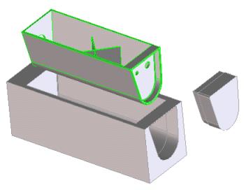
Mold Part (above), its Cavity (below), and Slider (right)
To create a core part,
1. Click Mold Design and then, in the Form Creation group, Core. The Create Core dialog box opens.
2. If necessary, specify any of the following parameters:
◦ Enter a name for the core part in the Name field.
◦ Specify an Owner for the core part.
◦ Specify the Mold Block containing the core.
◦ Specify the Pull Direction for the core, using the Direction 3D tool.
3. Specify the Core Feature on the part.
4. Specify the Parting Surface on the part.
5. To retain the core feature after the core part is created, click Keep Feat on.
6. Click OK to create the core part.
To create a cavity part,
1. Click Mold Design and then, in the Form Creation group, Cavity. The Create Cavity dialog box opens.
2. If necessary, specify any of the following parameters:
◦ Enter a name for the cavity part in the Name field.
◦ Specify an Owner for the cavity part.
◦ Specify the Mold Block containing the cavity.
◦ Specify the Pull Direction for the cavity, using the Direction 3D tool.
3. Specify the Cavity Feature on the part.
4. Specify the Parting Surface on the part.
5. To retain the cavity feature after the cavity part is created, click Keep Feat on.
6. Click OK to create the cavity part.
To create a slider,
1. Click Mold Design and then, in the Form Creation group,Slider. The Create Slider dialog box opens.
2. If necessary, specify any of the following parameters:
◦ Enter a name for the slider part in the Name field.
◦ Specify an Owner for the slider part.
◦ Specify the Mold Block containing the mold part.
3. Specify the Slider Feature on the part to place the slider part.
4. If necessary, specify the Direction of the slider, using the Direction 3D tool. By default, the direction is determined by the slider feature direction.
5. Specify the Fill Surface relative to the slider feature.
6. To retain the slider feature after the slider is created, click Keep Feat on.
7. Click Chk Undercut on to check the slider automatically for undercuts in the slider direction.
8. Click Next to create the current slider and continue creating sliders with the current settings, or click OK to end the operation.
To subtract a slider from the core or cavity part,
1. Click Mold Design and then, in the Form Creation group, Subtract Slider. The Subtract Slider dialog box opens.
2. Specify the Core/Cavity from which to subtract the slider.
 Core. The Create Core dialog box opens.
 Cavity. The Create Cavity dialog box opens.
 Slider. The Create Slider dialog box opens.
 Subtract Slider. The Subtract Slider dialog box opens.
 to complete the operation.