Different components are added to the mold using the same methodology.
To add new components, click Components and then in the Standard group, click New. The dialog box has following options:
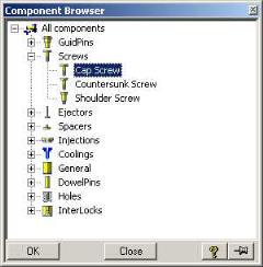
Component
The component browser is opened with the different component groups displayed. Press + to open a component group in the browser and select a component type.
Catalog
Modify the catalogue from which you choose the component. It defaults to the catalogue from which you built the initial mold base.
Position
Start Face
Define the starting face of the component(s) by selecting a face on a Plate or Insert. The component(s) is fixed to the specific Plate/Insert and subsequent modifications to the Plate or Insert will affect the component(s). This is the face on which the points will be created or the Workplane is projected (ref Points/Workplace options in next section). For ejectors this is automatically defined as bottom face of Plate 6. (It can be modified)
Position Access the positioning dialogue to position the component(s).
Component Parameters
Type
Depending on the component and the catalogue (that is, different types of screws for HASCO catalogue).
Cat Num
The component can be chosen through the CAT NUM. It will also reflect the component selected through any other method, and will be non-standard for non-standard dimensions. For ejectors this parameter will automatically reflect the next standard length using the L Proj or L To options in the Length parameter box under S1.
See Params
Press this button to activate and deactivate the component parameter scheme.
Ref is the part of the component positioned on the selected face.
Leading parameter is prefixed with a *.
Parameters
Groups together the Geometry and the Oversize parameters for the specific component. See the parameter scheme for the meaning of each value.
Following is a collection of all possible parameters depending on the component selected.
Geometric option
Use the arrow (when available) on the right of a value to select the standard values for this parameter. This value is also the leading dimension for the component. It is prefixed by a "*" on the parameter scheme. Each leading dimension has a set of dimensions automatically defined for each catalogue. Selecting the leading dimension will also select the set of standard dimensions, while updating the " Cat Num" parameter from the previous group.
Orientation field is only for displaying that the input is Defined. By pressing the button a sub dialog pops up:
V: The angle between the component direction and the X o Y plane of the Mold Coordinate System.
H: The angle of the projection of the component direction on the X o Y plane and the Z o X plane of the Mold Coordinate System.
Z: Rotation angle of component relative to the component direction.
Offset: Offset of the start point of the components from the start plane in the component direction.
Oversize option
Groups the oversize (hole clearance) dimensions. It includes the parameter names for which oversize values (to be added to the original parameter) exist. The default oversize values are determined according to the specific catalogue.
All Ins
If checked the group of components will be copied to all inserts in an insert sub assembly.
In this case the components will be added to the Component subassembly under the Ownership of the subassembly that contains the insert.
This option is active only if the group of components cuts only one insert.
The status of All Ins will be stored with the component group data.
Trim or Trim To: (Only for ejectors which cut core inserts)
Trim by: Trim ejector by surface. The maximum intersection point defines each ejector length.
Trim orth: Ejector is not trimmed. The minimum intersection point defines each ejector length.
When all the ejectors are not the same length then each component will be added as an individual group.
 New. The dialog box has following options: