Display options are provided in Creo Elements/Direct Finite Element Analysis to allow you to tailor the display of results. You could, for example, change the color range to show the results in grayscale. In this case, the corresponding contour map appearance also changes to grayscale.
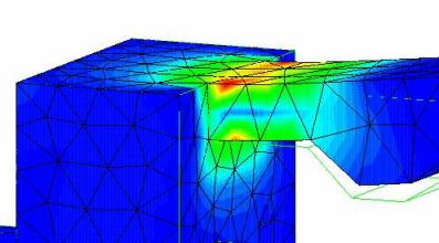
Von Mises Stress Contours: Full Range, Non-Continuous, Elem Edge On, Averaging On:
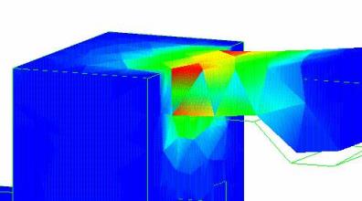
Von Mises Stress Contours: Full Range, Continuous, Elem Edge Off, Averaging Off:
To set the display options,
1. Click FEA and then, in the Post Process group, click the arrow next to Options.
2. Click Contour. The Contour dialog box opens.
3. If necessary, define the result.
4. Select the color range in the Color Range box.
5. Enter the number of colors you want in the No. Colors box. This sets the number of contours available.
6. Select the range method you want in the Range Meth box. The following ranges are available:
◦ Min-Max. This sets the minimum and maximum values.
◦ Min-Interval. This sets the minimum value and the result interval.
◦ Max-Interval. This sets the maximum value and the result interval.
◦ Full Range. This sets the range to the full range of values in the actual results component.
◦ From Matrl. This sets the maximum value to that of the used material.
When this range is selected (together with Dataset/Stress, Component/Von Mises), you can specify a material safety factor (the minimum value) in the Safety Fr box. (The material must have a Failure Stress value associated with it).
7. There are also input fields for the minimum and maximum result values for your contour range and the result interval between contours. Which of these fields are active depends on the range method you select.
8. If necessary, enter the required values in the Min, Max, and Interval boxes.
9. Select the display you want. The options available are:
◦ Continuous for a continuous color separation.
◦ Non Continuous for a non-continuous color separation.
10. Click the check boxes accordingly:
◦ Elem Edges. On - element edges are displayed.
◦ Averaging. On - the value at each node is averaged over adjacent elements. This is set to on by default for Creo Elements/Direct Finite Element Analysis. When Averaging is cleared, the values for each individual element, or element face, are displayed as contour colors. If you have quadratic elements, the averaging is still performed across elements. (This option is grayed-out if averaging does not apply to the selected dataset.)
◦ Part Edges. On - to display the edges of the deformed part.
◦ Error Est. On - to provide an error estimation of the analysis. This is valid for non- P-adaptive analyses. (P-adaptive analysis automatically provides an error estimation).
▪ This type of error estimation is only valid for datasets that can be averaged (for example stress, but not displacement).
▪ Error estimation and averaging are mutually exclusive.
▪ The legend of the contour map will be adjusted accordingly.
▪ If you have rough meshes within the first manual or automatic iteration, you are recommended to use the Non Continuous mode for the display method.
11. When you have set all your required options, click Update.
This will leave the dialog box open and allow you to try new options easily. Click to exit the menu.
To set deformation display options,
1. Click FEA and then, in the Post Process group, click the arrow next to Options.
2. Click Deformed. The Deformed dialog box opens. This allows you to tailor the appearance of results represented by deformation by scaling the results.
3. If necessary, click Result and specify the result.
4. Click Factor and enter a multiplication factor for your results in the Factor box.
5. Click Update to update.
To set the appearance of reaction-force symbols,
1. Click FEA and then, in the Post Process group, click the arrow next to Options.
2. Click Symbol. The Symbol dialog box opens.
3. If necessary, click Result and specify the result.
4. Click Factor and enter a multiplication factor for your symbols in the Factor box.
5. Click Color and specify the color of the symbols using the Color Selector.
6. Click Update to update.
To reset the display options,
1. Click FEA and then, in the Post Process group, click the arrow next to Options.
 to exit the menu.