When an analysis is performed, a results dataset is produced for each required result type you selected in the Define Job dialog box.
Using Results > Dataset in the Post Process group,, you can specify which results dataset you want to display.
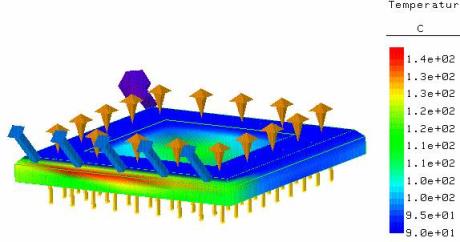
Dataset Results: Temperature
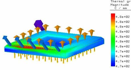
Dataset Results: Thermal Analysis Gradient
If you have performed a Modal or Linear Buckling analysis, in addition to selecting which type of results you want to display, you can also select individually for which mode the results should be displayed, using Results > Case Set.
Types of data available for post-processing
There are two categories of data produced by an analysis run:
• Primary data. These are the degree of freedom solutions calculated at each node (known as nodal solution data) and are calculated first. For structural analysis, these are the displacement results.
• Derived data. These are the results derived from the primary data; all the stresses, strains, strain energies and reactions. They are calculated per element or element face (known as element solution data) and can be represented as contour colors per element.
Certain derived data, such as stress, can also be averaged at the nodes (when they become nodal solution data). Averaged data are used to display the averaged contours in the results.
Result datasets available for display, and their components
Below is a list of all the possible types of result datasets available. The datasets that are actually available for you to display are dependent on the Required Results that you selected when setting up your analysis in the Define Job dialog box.
Included with the description of each result dataset is a list of the result components provided within that dataset.
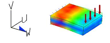
Stress and displacement directions are relative to the study coordinates that are displayed as shown (enlarged) in the following graphic.
• Stress, that is, the force per unit area producing deformation of a mesh element (can be averaged). This dataset has the following components:
◦ Von Mises. Von Mises stress is a commonly used failure criterion for ductile materials and is always a positive number, independent of the coordinate system used. It is calculated from all the normal stress and shear stress components for an element (i.e. all the Sigma values listed below).
◦ Max Shear. Maximum shear stress, i.e. the stress calculated with the results tensor rotated to the plane of maximum shear.
◦ Max Principal. Maximum principal stress, i.e. the stress calculated with the results tensor rotated to the plane of maximum principal stress (zero shear).
◦ Mid Principal. Middle principal stress, i.e. the stress calculated with the results tensor rotated to the plane with the middle principal stress value.
◦ Min Principal. Minimum principal stress, i.e. the stress calculated with the results tensor rotated to the plane with minimum principal stress.
◦ Sigma U The normal stress component for an element in the U direction.
◦ Sigma V The normal stress component for an element in the V direction.
◦ Sigma W The normal stress component for an element in the W direction.
◦ Sigma UV The shear stress component in the plane defined by the U-axis, in the Y direction.
◦ Sigma WU The shear stress component in the plane defined by the W-axis, in the U direction.
◦ Sigma VW The shear stress component in the plane defined by the V-axis, in the W direction.
• Displacement, that is, the displacement of a mesh element from its original unstressed position due to the applied load(s) as measured at the element nodes (cannot be averaged). This dataset has the following components:
◦ Magnitude The resultant displacement (vector?)
◦ Delta U The displacement component in the U direction of the results window.
◦ Delta V The displacement component in the V direction of the results window.
◦ Delta W The displacement component in the W direction of the results window.
• Strain, that is, the extension/compression of a mesh element in the direction of the applied stress (can be averaged.). This dataset has the following components:
◦ Von Mises. Von Mises strain is a commonly used failure criterion for ductile materials and is always a positive number, independent of the coordinate system used. It is calculated from all the normal strain and shear strain components for an element (i.e. all the Epsilon values listed below).
◦ Max Shear. Maximum shear strain, i.e. the strain calculated with the results tensor rotated to the plane of maximum shear.
◦ Max Principal. Maximum principal strain, i.e. the strain calculated with the results tensor rotated to the plane of maximum principal stress (zero shear).
◦ Mid Principal. Middle principal strain, i.e. the strain calculated with the results tensor rotated to the plane with the middle principal stress value.
◦ Min Principal. Minimum principal strain, i.e. the strain calculated with the results tensor rotated to the plane with minimum principal stress.
◦ Epsilon U . The normal strain component for an element in the U direction.
◦ Epsilon V. The normal strain component for an element in the V direction.
◦ Epsilon W. The normal strain component for an element in the W direction.
◦ Epsilon UV. The shear strain component in the plane defined by the U-axis, in the V direction.
◦ Epsilon WU. The shear strain component in the plane defined by the W-axis, in the U direction.
◦ Epsilon VW. The shear strain component in the plane defined by the V-axis, in the W direction.
• Reaction Force. The forces encountered at the constraint locations to keep the part in equilibrium. This dataset has the following components:
◦ Magnitude. The resultant force.
◦ Force U. The force component in the U direction.
◦ Force V. The force component in the V direction.
◦ Force W. The force component in the W direction.
• Applied Force, that is, the calculated force at the mesh nodes of a vertex, edge or face to which you have applied a force for the analysis (cannot be averaged).
• Element Force. The calculated forces applied to the individual mesh elements during the analysis (cannot be averaged).
• Strain Energy. The energy required to produce the calculated strain in the individual elements. Identifying the areas of highest strain energy in your part provides an excellent indication of the areas that would benefit most from design changes (can be averaged).
• Strain Energy Density. The strain energy per unit volume. This can provide a clearer picture than Strain Energy in cases where you have conditioned the mesh since it removes the complication of different size elements (can be averaged).
• Temperatures. The temperature distribution (cannot be averaged).
• Applied Flow. The applied heatflow (cannot be averaged).
• Bnd Convection. The boundary convection.
• Thermal Analysis Gradient. The resultant temperature gradients (can be averaged). This dataset has the following components:
◦ Magnitude The resultant temperature.
◦ Gradient U The temperature component in the U direction.
◦ Gradient V The temperature component in the V direction.
◦ Gradient W The temperature component in the W direction.
• Thermal Analysis Flux. The resultant heat flux through a part (can be averaged). This dataset has the following components:
◦ Magnitude The resultant temperature.
◦ Flux U The heat flux component in the U direction.
◦ Flux V The heat flux component in the V direction.
◦ Flux W The heat flux component in the W direction.
• Error. Error estimation for p-element analysis.
• PU order. Final element order in U-direction for p-element analysis.
• PV order. Final element order in V-direction for p-element analysis.
• PW order. Final element order in W-direction for p-element analysis.
To select a dataset to display,
The Dataset dialog box allows you to select which of the datasets requested in your study are to be displayed and to choose the way in which they are represented.
To access the Dataset dialog box:
1. Click FEA and then, in the Post Process group, click the arrow next to Results.