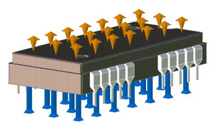
Creo Elements/Direct Finite Element Analysis lets you apply thermal loads in the form of heatflows on vertices, edges, and faces. The following figure shows a fixed-temperature boundary condition set on the top face and a heatflow load applied to the bottom face.
To set a heatflow on a vertex,
1. Click FEA and then, in the Thermal LBC group, click Loads. The Thermal Loads dialog box opens.
2. Click Vertex in Heatflow. The Vertex Heatflow dialog box opens.
3. If necessary, give the study a name.
When no name has been earlier provided, you can click Study and enter a new one in the highlighted box.
a. Click Name. Creo Elements/Direct Finite Element Analysis suggests a name for the current heatflow in the Name box. You can accept the proposed name or type a new one in the highlighted box.
b. Click Ref Vertex and specify the vertex on your design model where you want to apply the heatflow.
c. Enter a value in the Value box.
4. Click Next to remain in the dialog box and define additional heatflows or click to apply the heatflow.
To set a heatflow on an edge,
1. Click FEA and then, in the Thermal LBC group, click Loads. The Thermal Loads dialog box opens.
2. Click Edge in Heatflow. The Edge Heatflow dialog box opens.
3. If necessary, give the study a name.
When no name has been earlier provided, you can click Study and enter a new one in the highlighted box.
4. Click Name. Creo Elements/Direct Finite Element Analysis suggests a name for the current heatflow in the Name box. You can accept the proposed name or type a new one in the highlighted box.
5. Click Ref Edge and specify the edge on your design model where you want to apply the heatflow.
6. Enter a value in the Value or Total Value box.
7. Click Next to remain in the dialog box and define additional heatflows or click to apply the heatflow.
To set a heatflow on a face,
1. Click FEA and then, in the Thermal LBC group, click Loads. The Thermal Loads dialog box opens.
2. Click Face in Heatflow. The Face Heatflow dialog box opens.
3. If necessary, give the study a name.
When no name has been earlier provided, you can click Study and enter a new one in the highlighted box.
4. Click Name. Creo Elements/Direct Finite Element Analysis suggests a name for the current heatflow in the Name box. You can accept the proposed name or type a new one in the highlighted box.
5. Click Ref Face and specify the face on your design model where you want to apply the heatflow.
6. Enter a value in the Value or Total Value box.
7. Click Next to remain in the dialog box and define additional heatflows or click to apply the heatflow.
To set heat generation,
This is heat being generated by a part and similar to a heat sink. First set a temperature boundary condition and then give the part a value for the heat the part is generating. The face is maintained at the temperature boundary condition you set and Creo Elements/Direct Finite Element Analysis calculates the part's heat flux and temperature distribution.
1. Click FEA and then, in the Thermal LBC group, click Loads. The Thermal Loads dialog box opens.
2. Click Part in Heat Generation. The Heat Generation dialog box opens.
3. If necessary, give the study a name.
When no name has been earlier provided, you can click Study and enter a new one in the highlighted box.
4. Click Name. Creo Elements/Direct Finite Element Analysis suggests a name for the current heat generation constraint in the Name box. You can accept the proposed name or type a new one in the highlighted box.
5. Click Part and specify the part.
6. Enter a value in the Value or Total Value box.
7. Click Next to remain in the dialog box and define additional heat generation values or click to apply the heat generation.
Temperature-dependent heat generation
An additional feature of FE Analysis's heat generation functionality is being able to set temperature-dependent heatflows. When you click the Temp Dependent check box, Creo Elements/Direct Finite Element Analysis expands the Heat Generation dialog box to include the following:
Temperature
This is where you enter the part temperature.
Incrmnt
Increments the temperature entry by a specified value.
Factor
Increases the heatflow value by a specified factor. It is particularly useful when putting entries into the Heat Generation Table.
Delete Entry
Deletes an entry from the Heat Generation Table. First highlight an entry and click Apply to transfer the values to the Heat Generation dialog box. (You can also double-click the entry.) Click Delete Entry to delete the entry from the table.
Set Entry
Sets an entry in the table.
Evaluate
Evaluates the heatflow for all table entries using the temperature value and the factor.
The Heat Generation Table is also displayed showing the following information:
Temperature
Shows the fixed temperature you entered.
Factor
Shows the current factor. When you click Evaluate in the Heat Generation dialog box, the heatflow is multiplied by the factor (the factor then resets to 1).
 to apply the heatflow.