2. Click Interface and then, in the Library group, click the arrow next to Parts.
3. Click Define connector. The Define Component dialog box opens.
4. The connector has rectangular holes so you must select Rectangular Pin in the Set Pin Faces section. Now Creo Elements/Direct Cabling can locate the center of the rectangle when placing wires in holes.
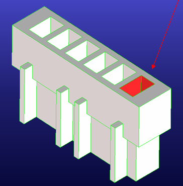
5. To automatically find rectangular pin holes, you can define the wire insertion direction of the pins. Click Wire Insert Dir, then position the arrow on the face shown here:
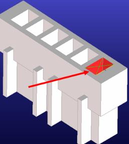
6. To define the first pin, click Straight Edge and select one of the straight edges defining the pin hole marked in red. Creo Elements/Direct Cabling automatically finds the connected edges of the rectangular shape and marks it with an X to show that it recognizes the pin hole.
7. Select 1 from the Pin Nr menu.
8. Click Next Pin. The Pin Nr field automatically increases by one and pin 2 is ready to define.
9. Click Straight Edge and select the next pin in the viewport.
10. Define the remaining pins.
11. Click OK to complete the operation.
Your defined your new connector. Next you will learn how to view the pin definitions for a defined connector.
 Parts.
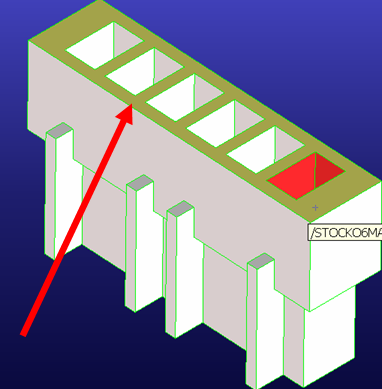
 to complete the operation.