Check and validate Creo Elements/Direct Machining features
Creo Elements/Direct Machining features (in this case, machined holes) are checked for validity with each command. If a Creo Elements/Direct Machining feature has been invalidated, it is no longer checked automatically until you export it to a CAM system or manually re-validate the feature.
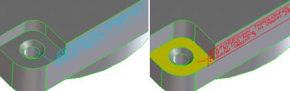
The following graphic shows a machined hole that is now invalid because the supporting face was offset (Click Modeling and then, in the Modify 3D group, click the arrow next to More. Click Offset.). Notice how the feature text turns red (as does the feature name in the browser.
To validate a single feature (a machined hole),
1. Click Feature and then, in the Custom Feature group, click the arrow next to More.
2. Click Check Single.
3. Select the machined hole to re-validate using one of the following methods:
◦ Click the feature or its label.
◦ Use the Select tool to select a single feature.
◦ Use the Structure Browser to select a single feature. (Make sure that the Feat's option is switched on in the browser.)
4. Once you have selected the feature, Creo Elements/Direct Machining will try to re-validate the feature.
To check and validate multiple features,
Creo Elements/Direct Machining lets you:
• Check the validity of features which have been invalidated by previous modeling steps
• Check distances between adjacent features
• Check the part to which features are applied (for example, in order to check for minimal wall thickness)
• Generate a report highlighting problems that need to be eliminated in order to ensure a smooth transfer to a CAM System.
Check multiple features:
1. Click Feature and then, in the Custom Feature group, click the arrow next to More.
2. Click Check Multiple. The Check Features dialog box opens.
3. Under Select Features By, check one of the buttons.
4. Under Filter Methods, check one of the buttons.
5. Under Operations, specify the type of distance from the selection box.
◦ Chk&Fix: The features are checked and inconsistencies are resolved.
◦ Shell: A shell of given thickness is created around every feature.
◦ Core: A kind of core is built for every feature.
◦ Offset: The core is enlarged by the given distance.
◦ Report: The features are checked and inconsistencies are reported.
6. For Shell or Offset, specify the thickness of the security zone.
7. Once you complete the command, Creo Elements/Direct Machining attempts to validate the features. A part is created for every valid feature in order to check interference on a visual basis or with other tools like Clash.
In the case of threads, which are incorporated on a core-diameter basis into the model, the generated parts use the outer diameter of the thread when checking to see whether a threaded hole is touched by other features.
Validate a set of Creo Elements/Direct Machining features:
This command is provided for compatibility reasons with previous versions:
1. Enter MACHADV_FEAT_VALIDATE into the user input line
2. Select the Creo Elements/Direct Machining features to be re-validated using one of the following methods:
◦ Click the feature or its label.
◦ Use the Select tool to select the feature(s).
◦ Use the Structure Browser to select the feature(s). (Make sure that the Feat's option is switched on in the browser.)
You can use the Filter Methods to help you with selecting the features. You can filter the Creo Elements/Direct Machining features by choosing from the following:
◦ All
◦ Category
◦ Reference feature
3. Once you have selected the feature, Creo Elements/Direct Machining attempts to validate the feature.
 Check Single.
 Check Multiple. The Check Features dialog box opens.