The settings described in this section are valid for the current session only unless you choose to save them to the environment.
Setting feature short name
Creo Elements/Direct Machining can be customized by specifying company-specific shorthand-texts for the different features. You do this by using the Creo Elements/Direct Machining Integration Kit functionality described within the customization section or directly from the user interface. The feature abbreviations are shown in the browser.
To specify a short name (user interface method) :
1. Click File > Settings > Machining > Set Machining Feature Short Name. The Short Name dialog box and the Custom Process browser opens.
2. Select a feature type from the browser (or enter its name in the user input line). See the customization section for the names of the features.
3. The current abbreviation is displayed in the data field adjacent to the ShortName button.
4. Enter the new name in the Abbrev data entry field or in the user input line (for example, CSK-Type-10mm).
5. Click OK to replace the current abbreviation by the new one.
Click Reset to reset the abbreviation text back to its default setting.
Setting feature flag texts
Creo Elements/Direct Machining can be customized by specifying company specific texts for the feature flags for the different features. You do this by using the Creo Elements/Direct Machining Integration Kit functionality described within the customization section or directly from the user interface.
To set a flag text (user interface method) :
1. Click File > Settings > Machining > Set Machining Feature Flag Texts. The Feature Flag dialog box and the Custom Process browser opens.
2. Select a feature type from the browser (or enter its name in the user input line). See the customization section for the names of the features.
3. The current flag text is displayed in the data field adjacent to the Flag String button.
4. Specify the new text by typing into this field or click the Flag String button. A text edit window opens containing the current flag text. Edit the current text and click Apply. Click Clear to clear the edit window.
Do not delete the {1} ... {n} specifiers in the flag text otherwise the dialog will not replace the strings.
5. Click OK to replace the current flag text with the new text.
Click Reset to reset the flag text back to its default setting.
Setting automatic acquisition of values
By default, Creo Elements/Direct Machining:
• Grabs the position of the axis when you specify a point on the face.
• Does not display the parameter sketches.
• Does not display the tolerance and surface quality input fields.
• Does show the flag label initially.
Default Settings: CenPnt and Axis Switched On
To change the default settings:
1. Click File > Settings > Machining > Set Machining Dialog Defaults. The Defaults dialog box opens.
2. Simply click the setting on or off to toggle the status of the settings or change to another option presented within the Defaults dialog box.
3. Click OK to replace the current settings with the new settings.
Set the following:
• To switch on the automatic acquisition of the center point from the selection of the face, click CenPnt.
• To switch on the automatic acquisition of the axis direction from the selected face at the selected position, click Axis.
• To display the tolerance and surface quality buttons automatically in the relevant menus, click Tol & Qual.
• To show the graphical representation of the machined feature automatically, click Show Img.
• To hide the flag label automatically, clear the Flag Vis check box.
• The volume feedback for all the holes from the moment enough data are entered to compute and display such a feedback is customizable. The feedback is adapted for each changed or newly entered parameter. The higher levels of feedback gives a better visualization but of course take more time to compute. There are 4 levels
Value
Description
Off
Neither feedback calculation nor display
Raw
Feedback is only calculated in terms of the intersection of the axis of the hole and the other faces of the part, the display will be built upon those data
Adjusted
(Default)
Feedback is calculated in terms of the intersection of the cylindrical or conical side surfaces of the hole and the other faces of the part, the display will be built upon those data.
• The type of point decoder displayed upon selection of planar faces can be customized:
Value
(Keyword)
Description
uv
:uv
The point decoder uses a 2d coordinate system on the planar surface.
3d
:3d
The point decoder uses a 3d coordinate system on the planar surface.
hidden
:hidden
No point decoder is displayed, but you can access the point decoder using the context menu.
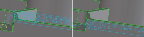
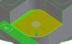
Safety zones visible within feedback
If you wanted to check, whether features are too close together or too close to an edge or face within OSD 2002+, you had to create the feature first and then do a check by creating the necessary offsets by using the Check functions supplied by the module.
With OSD 2003 there is a new feedback capability implemented, which allows to display safety zones around the the feature already within the creation or modification command. You can define the thickness of those safety zones within the commands. As with the normal volume feedback within the Creo Elements/Direct Machining Module, those safety zones will be displayed as soon as the user has entered enough data to compute those safety zones.
The feedback will mainly aide visual detection of problematic zones, but there are some problems detected computationally as well, which will result in warning or error messages.
This safety zone doesn't show problems, due to the curved start face it is pulled up front a little bit with respect to the hole feature
Increasing the thickness of the safety zone around the counterbore, you will see the safety zone "jumping" in reverse axis direction once it starts touching other faces of the part. You may want to avoid such a situation because of space needed for assembly or to avoid notch effects.
Stepped Hole Defaults
If you create a stepped hole, you can reuse as much information as possible when you define the individual steps. The amount of information that you can reuse differs with respect to the situation. Therefore, the dialog acquiring the dialog defaults has been extended by the following options:
Dialog Field
(Keyword)
Type
Description
Diameter Tolerance
(:use_diameter_tolerance)
boolean
Use the diameter tolerance of the actual step as default for the next step.
Partial Depth
(:use_partial_depth)
boolean
Use the partial depth of the actual partially toleranced or partially threaded hole step as default for the next step, if another partially toleranced or partially threaded step is created.
Partial Depth Tolerance
(:use_partial_depth_tolerance)
boolean
Use the partial depth tolerance of the actual partially toleranced or partially threaded hole step as default for the next step, if another partially toleranced or partially threaded step is created.
Blind Hole Depth
(:use_blind_hole_depth)
boolean
Use the depth of the actual blind hole step as default for the next step, if the next step is a blind or through hole step.
Blind Hole Depth Tolerance
(:use_blind_hole_depth_tolerance)
boolean
Use the depth tolerance of the actual blind hole step as default for the next step, if the next step is a blind or through hole step.
Max Depth as Hole Depth
(:use_max_depth_as_through_hole_depth)
boolean
Use the maximum depth as default depth of a through hole step.
Through Hole Depth
(:use_through_hole_depth)
boolean
Use the depth of the actual through hole step as default for the next step, if the next step is a blind or through hole step.
Through Hole Depth Tolerance
(:use_through_hole_depth_tolerance)
boolean
Use the depth tolerance of the actual through hole step as default for the next step, if the next step is a blind or through hole step.
Reusing the blind hole depth or reusing the through hole depth means that the depth of a blind hole will be used as a default for the next step regardless of the type that is created. The Type column specifies the type to fetch from and not the type to propagate to. The settings will be stored within Product Development System (PDS).
Setting face colors
Use the Face Colors menu to set the colors of machined faces. Colors are automatically assigned to indicate that the face has been assigned a thread, surface quality, or a tolerance. Click File > Settings > Machining > Set Machining Face Colors. The Face Colors dialog box opens. The default settings are:
• Thread: Blue for threaded holes.
• SfQuality: Green for surface quality factors.
• Tolerance: Dark red for tolerance values.
Activating and deactivating adapters
When you start Creo Elements/Direct Machining it activates export adapters or links as specified within the ma_customize file.
Export Adapters must be activated in order for you to see them in the File / Save list of file formats.
To activate and deactivate export adapters from the user interface:
1. Click File > Settings > Machining > Machining Adapters. The Adapters dialog box and the Adapters browser opens. The Adapters dialog box contains a list of available export adapters together with their actual status.
2. Simply double-click an entry to select it (or select it and click Apply).
3. Click OK to activate or deactivate the export adapter.
• If you deactivate Creo Elements/Direct Machining, all active export links are also deactivated (the licenses will be released). However, Creo Elements/Direct Modeling remembers that those links were active and attempts to reactivate them if the Creo Elements/Direct Machining module is activated.
• Remember to save part/assembly data in the usual manner. This is because only feature information is exported when you use the export adapters are meant for data-exchange not for storage.
Adapter status
This table shows the current status (active or inactive) of installed adapters. See above to find out how to activate/deactivate an adapter.
Setting machining export parameters
You can specify parameters for machining information that is embedded in the adapter files during export; information such as:
• Adapter,
• A precision value,
• Export format for a double precision value, and
• Whether the thread type is exported or not.
To set machining export parameters,
1. Click File > Settings > Machining > Machining Export Settings. The Exp.Settings dialog box and the Adapters browser open. The Adapters browser contains a list of available export adapters.
2. In the Adapters browser, double-click an adapter to select it (or select it and click Apply).
3. In the Exp.Settings dialog box, in the Precision box, specify an export precision value. The exported precision value should be between 0 and 16.
4. Specify an export format for double-precision values (a maximum data size of 8 bytes):
◦ Automatic: Double precision values are exported according to the default settings.
◦ Fixed: Double precision values are exported in the absolute format; for example, 0.00001234.
◦ Scientific: Double precision values are exported in the exponential format; for example, 1.234e-05.
5. Specify whether the thread type is exported or not:
◦ Default: The thread type is exported according to the default settings.
◦ No: The thread type is not exported.
◦ Yes: The thread type is exported; for example, BSW (British Standard Whithworth Thread), BSF (British Standard Fine Thread), or BSP (British Standard Pipe Thread).