Dialog Field (Keyword) | Type | Label | Description | ||
|---|---|---|---|---|---|
TAP Units (TAP_UNITS) | Keyword | :METRIC :INCH :BSW :BSF :BSP :UNC :UNF :NPT :PIPE_RP :PIPE_G :TRAPEZOID :FLAT_TRAPEZOID :SAW :ROUND :ROUND_MINING :EDISON :PIPE_JIS_B_0203 :PIPE_PG :METRIC_FINE The default is :METRIC threads, if you have a metric length unit set within Creo Elements/Direct Modeling and :INCH if you have set an imperial length unit. | |||
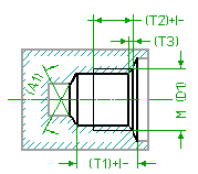
ThreadDia (THREAD_DIA) | Length | D1 | The nominal diameter of the thread. | ||
ThreadSize (THREAD_SIZE) | Length | The pitch of the thread. | |||
ThreadTpi (THREAD_TPI) | Number | Alternative method to specify the pitch of the thread by entering the Thread Per Inch value for all imperial style threads and pipe threads. | |||
Starts (THREAD_STARTS) | Number | The number of thread starts. This value has no effect upon the geometrical representation of the threaded hole, but the data is needed for complete specification of the thread in order to create correct manufacturing documents. The default is 1. | |||
Direction (THREAD_HAND) | Keyword | The direction of the thread. This value has no effect upon the geometrical representation of the threaded hole, but the data is needed for complete specification of the thread in order to create correct manufacturing documents. The following keywords are possible : :RIGHT (the default) :LEFT | |||
Nom.PipeDia. (NOMINAL_PIPE_DIA) | Length | The nominal diameter of a pipe thread, which is not the "outer" diameter of the thread. This value has no effect upon the geometrical representation of the threaded hole, but the data is needed for complete specification of the pipe thread in order to create correct manufacturing documents. | |||
Drill Dia (DRILL_DIA) | Length | The diameter of the hole to be drilled. | |||
Tap Depth (TAP_DEPTH) | Toleranced Length | T2 | The depth of the thread. If you have added a tolerance to this parameter through the Creo Elements/Direct Annotation 3D module or by direct specification within the dialog box, it is written into the output file to be transferred to the receiving CAM system (in either ISO or values). See the Description about specifying the Tolerance of a length value for further information. Normally, the tap depth (a parameter) is derived from the thread diameter and set to a default value by the system (Creo Elements/Direct Modeling). The value is slaved to the drill depth, unless explicitly set.
If the drill depth is changed when still slaved to the tap depth, the tap depth is recalculated again by subtracting the standard tap clearance from the drill depth. | ||
DrillDepth (DRILL_DEPTH) | Toleranced Length | T1 | Specifies the drilling depth. The depth is defined as the length of the drilled cylinder and does not include the tip of the drill tool. If you have added a tolerance to this parameter through the Creo Elements/Direct Annotation 3D module or by direct specification within the dialog box, it is written into the output file to be transferred to the receiving CAM system (in either ISO or values). See the Description about specifying the Tolerance of a length value for further information. See also
Meas Mode. Normally, the drill depth is derived from the thread diameter and the hidden customization value, standard tap clearance (STD_TAP_CLEARANCE). The drill depth (a parameter) is set to a default value by the system (Creo Elements/Direct Modeling). The value is slaved to the tap depth, unless explicitly set.
If the tap depth is changed when still slaved to the drill depth, the drill depth is recalculated again by adding the standard tap clearance to the tap depth. | ||
Cone Angle (CONE_ANGLE) | Angle | A1 | The tip angle of the drill tool to be used for the drilling operation. A 118 degree default is used. The following restrictions apply: 0 < A1 <= 180 degree, that is, you can create a flat blind hole, but there are special commands to do so (simply replace the BLINDHOLE by FLAT_BLINDHOLE in the name of the command). | ||
Cham Depth (CHAMFER_DEPTH) | Length | T3 | The depth of the chamfer measured in the direction of the axis. | ||
Cham.Angle (CHAMFER_ANGLE) | Angle | The tool tip angle of the sink tool. |
Dialog Field (Keyword) | Type | Label | Description |
|---|---|---|---|
ThreadTpi Numerator (THREAD_TPI_NUM) | Non-negative Number | The numerator part of a rational thread per inch value for the thread pitch. This parameter is applicable to :NPT and :UNC type threads. For other type of threads, if a positive value occurs in a customization table, then the numerator value is forced to zero. | |
ThreadTpi Denominator (THREAD_TPI_DEN) | Positive Number | The denominator part of a rational thread per inch value for the thread pitch. This parameter is applicable to: NPT and :UNC type threads. For other type of threads, if the value in a customization table is greater than one, then the denominator value is forced to one. |
Dialog Field (Keyword) | Type | Label | Description |
|---|---|---|---|
(STD_TAP_CLEARANCE) | Positive Number | The difference between the drill depth and the tap depth. |
Dialog Field (Keyword) | Description |
|---|---|
Show/Hide Image (IMAGE_SHOWN) | Shows or hides the graphical representation of the machined hole. |
Show/Hide Tolerance & Quality (TOLERANCE_AND_QUALITY) | Shows or hides additional tolerance-related input fields. |