Dialog Field (Keyword) | Type | Label | Description | ||
|---|---|---|---|---|---|
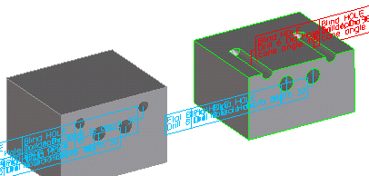
Face (SEL_FACE) | Specifies the face for the drilling operation. Clicking a face automatically derives values for CenterPt and Axis Dir (providing you have not deactivated automatic parameter acquisition). | ||||
Center Point (CEN_PNT) | 3D Position | Specifies the center point for the drilling operation. If the starting face is deleted later by other machining operations, the center point may be left hanging in space. If you click Face and click a point on a face, the center point is derived from this point (providing you have not deactivated automatic parameter acquisition). | |||
Axis (AXIS) | 3D Axis (Direction + Position + Up-Direction) | Specifies the axis for the machined hole. If the starting face is deleted later by other machining operations, the center point may be left hanging in space. If you click Face and click a point on a face, the axis is derived normal to this point (providing you have not deactivated automatic parameter acquisition). | |||
TAP Units (TAP_UNITS) | Keyword | Currently, the following threads are supported : :METRIC :INCH :BSW :BSF :BSP :UNC :UNF :NPT :PIPE_RP :PIPE_G :TRAPEZOID :FLAT_TRAPEZOID :SAW :ROUND :ROUND_MINING :EDISON :PIPE_JIS_B_0203 :PIPE_Pg :metric_fine The default is metric threads, if you have a metric length unit set within Creo Elements/Direct Modeling and :inch if you have set an imperial length unit. | |||
Thread Diameter (THREAD_DIA) | Length | D1 | The nominal diameter of the thread. | ||
Thread Pitch (THREAD_SIZE) | Length | The pitch of the thread. | |||
ThreadTpi (THREAD_TPI) | Number | Alternative method to specify the pitch of the thread by entering the Thread Per Inch value for all imperial style threads and pipe threads. | |||
Starts (THREAD_STARTS) | Number | The number of thread starts. This value has no effect upon the geometrical representation of the threaded hole, but the data is needed for complete specification of the thread in order to create correct manufacturing documents. The default is 1. | |||
Direction (THREAD_HAND) | Keyword | The direction of the thread. This value has no effect upon the geometrical representation of the threaded hole, but the data is needed for complete specification of the thread in order to create correct manufacturing documents. The following keywords are possible : :right (the default) :left | |||
Nom.PipeDia. (NOMINAL_PIPE_DIA) | Length | The nominal diameter of a pipe thread, which is not the "outer" diameter of the thread. This value has no effect upon the geometrical representation of the threaded hole, but the data is needed for complete specification of the pipe thread in order to create correct manufacturing documents. | |||
Drill Diameter (DRILL_DIA) | Length | The diameter of the hole to be drilled. | |||
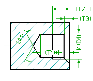
Tap Depth (TAP_DEPTH) | Toleranced Length | T2 | The depth of the thread. If you have added a tolerance to this parameter through the Creo Elements/Direct Annotation 3D module or by direct specification within the dialog box, it is written into the output file to be transferred to the receiving CAM system (in either ISO or values). Normally, the tap depth (a parameter) is derived from the thread diameter and set to a default value by the system (Creo Elements/Direct Modeling). The value is slaved to the drill depth, unless explicitly set.
If the drill depth is changed when still slaved to the tap depth, the tap depth is recalculated again by subtracting the standard tap clearance from the drill depth. | ||
Drill Depth (DRILL_DEPTH) | Toleranced Length | T1 | Specifies the drilling depth. The depth is defined as the length of the drilled cylinder and does not include the tip of the drill tool. If you have added a tolerance to this parameter through the Creo Elements/Direct Annotation 3D module or by direct specification within the dialog, it is written into the output file to be transferred to the receiving CAM system (in either ISO or values). Normally, the drill depth is derived from the thread diameter and the hidden customization value, standard tap clearance (STD_TAP_CLEARANCE). The drill depth (a parameter) is set to a default value by the system (Creo Elements/Direct Modeling). The value is slaved to the tap depth, unless explicitly set.
If the tap depth is changed when still slaved to the drill depth, the drill depth is recalculated again by adding the standard tap clearance to the tap depth. | ||
Cone Angle (CONE_ANGLE) | Angle | A1 | The tip angle of the drill tool to be used for the drilling operation. A 118 degree default is used. The following restrictions apply 0 < A1 <= 180 degree. i.e. you can create a flat blind hole, but there are special commands to do so (simply replace the BLINDHOLE by FLAT_BLINDHOLE in the name of the command) | ||
Chamfer Depth (CHAMFER_DEPTH) | Length | T3 | The depth of the chamfer measured in direction of the axis. | ||
Chamfer Angle (CHAMFER_ANGLE) | Angle | The tool tip angle of the sink tool. | |||
Name (NAME) | String | Specifies the name of the new feature. In case of modify this name is fixed, to modify the name of a feature please use rename. | |||
Flag DP (FLAG_DP) | The docuplane which should own the flag text. If you switch on the variable for the first time within a dialog box, the computed defaults will be activated. If you decide not to use the docuplane for the flag text but want to get a free flag text, simply switch off the variable. You can reactivate your last value (within the same dialog box) later by switching it on again | ||||
Depth DP (DEPTH_DP) | The docuplane which should own the depth related dimensions. If you switch on the variable for the first time within a dialog, the computed defaults will be activated. If you decide not to use the docuplane for the dimensions but want to get a free dimensions, simply switch off the variable. You can reactivate your last value (within the same dialog box) later by switching it on again | ||||
DriDeSfty (DRILL_DEPTH_SAFETY_ZONE_THICKNESS) | Length | The thickness of the depth related safety zone (i.e. the wall thickness of the conical tip) If you decide not to use the safety zone, simply switch off the variable. You can reactivate your last value (within the same dialog box) later by switching it on again. | |||
DiaSfty (DRILL_DIA_SAFETY_ZONE_THICKNESS) | Length | The thickness of the diameter related safety zone (that is, the wall thickness of the "pipe" around the hole) If you decide not to use the safety zone, simply switch off the variable. You can reactivate your last value (within the same dialog box) later by switching it on again. |
Dialog Field (Keyword) | Type | Label | Description |
|---|---|---|---|
(THREAD_TPI_NUM) | Non-negative Number | The numerator part of a rational thread per inch value for the thread pitch. This parameter is applicable to :NPT and :UNC type threads. For other type of threads, if a positive value occurs in a customization table, then the numerator value is forced to zero. | |
(THREAD_TPI_DEN) | Positive Number | The denominator part of a rational thread per inch value for the thread pitch. This parameter is applicable to :NPT and :UNC type threads. For other type of threads, if the value in a customization table is greater than one, then the denominator value is forced to one. |
Dialog Field (Keyword) | Type | Label | Description |
|---|---|---|---|
(CHAM_DIA) | Non-negative length | An alternative method to specify the depth of the front chamfer. If the SEL_FACE face is in a plane that is perpendicular to the axis of the hole, then the chamfer radius is the half of the hole diameter. | |
(STD_TAP_CLEARANCE) | Positive Number | The difference between the drill depth and the tap depth. |
Dialog Field (Keyword) | Description |
|---|---|
Show/Hide Image (IMAGE_SHOWN) | Shows/hides the graphical representation of the machined hole. |
Show/Hide Tolerance & Quality (TOLERANCE_AND_QUALITY) | Shows/hides additional tolerance-related input fields. |
Next (NEXT) | Completes the current operation and prompts you for the next location (create, copy) or feature (modify) without closing the dialog box. |