Why is there a hole depth or a drill depth for through holes ?
If you change the value for the hole depth, it doesn't look like the new value has any significance. The part is drilled through, and you will not create a blind hole by using smaller values.
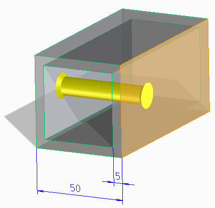
Fig 1: Preview of Countersunk Through Hole
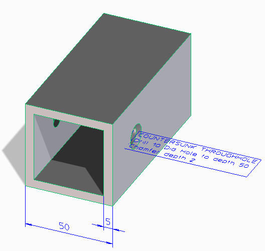
Fig 2: Countersunk Through Hole after completing the operation
With the square profile above, there are two valid values for the depth of the drill operation, depending whether you want to drill through the whole profile or only the first wall. To make it easier to enter meaningful values the Creo Elements/Direct Machining module displays a preview of the hole in the viewport (as shown in the Fig 1) and displays the computed values in the Countersunk Through Hole dialog box. After creating the Countersunk Through Hole, a label displays the hole type and the computed values as shown in Fig 2. The default behavior is to use the smallest value.
Why is there a second full circle for a threaded hole ?
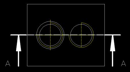
If you generate views of parts with threaded holes, you will see a situation such as depicted in the left half of the image below. Normally, a threaded hole is displayed as in the right half of the image.
The difference becomes clear if you look at the section view below.
Normally a threaded hole is only chamfered up to the nominal diameter of the thread (situation on the right side). The tables delivered with the Creo Elements/Direct Machining module specify a deeper chamfer (left side) in order to allow easier assembly with standard screws; however, this jeopardizes threads and screws carrying dynamic loads. Thus, both halves of the drawing are correct. You can even customize the Creo Elements/Direct Machining module so you can switch between both versions of the hole.
Why is there no effect visible when changing a thread data table ?
If you want to change the thread data tables used by the Creo Elements/Direct Machining module, please be aware that you have to make the same changes to two tables "...-tap-..." and "...-thread_dia-...", otherwise you will see various types of inconsistency. This method of implementation was necessary to facilitate upward compatibility between older versions of the Creo Elements/Direct Machining module (that only allow a fixed set of holes), and newer versions that allow many different combinations of thread size and diameter. You can also specify different diameter thread size combinations within one table of the Creo Elements/Direct Machining Module (e.g., "M 12 x 1.75" and "M 12 x 1.5").
Why is there no change back to a blind hole by Modify if the hole became a through-hole ?
1. What happened when drilling the blind_hole ?
If you drill a blind hole too deep so that it becomes a through-hole, the cone_angle (of the drill tip) parameter of the blind hole is modified to 180 degrees. This means implicitly that you have created a through-hole.
The same change to cone_angle 180 degree is performed if you cut the end of the hole away with a Boolean operation.
2. Why does a blind hole behave differently than a flat blind hole ?
The flat versions of blind holes will remember that they are only allowed to have a flat bottom (cone_angle = 180 degrees) or no bottom and they will recreate the flat bottom when modified to smaller values (that require a flat bottom).
All the other blind holes, which have a user defined cone_angle cannot retain the value of the cone_angle at the time they were created, because the cone_angle is subject to be changed by local operations.
How to customize Creo Elements/Direct Machining to create small chamfers or large chamfers with threaded holes ?
You can specify different sets of value combinations within the threaded hole area. The only necessary condition is that you have a unique string for the "tap" key.
Why is there no support for DIN/ANSI Standard values within the tables of the Creo Elements/Direct Machining module ?
The reason for this is Copyright. Creo Elements/Direct would need to charge and pay royalties to put them in as part of the package. Customers can add ANSI or DIN features as long as they have paid the appropriate standards organization.
Why is there no 1:1 relation between the features seen by the CAM system and those within Creo Elements/Direct Modeling ?
To explain this behavior a short overview about the Creo Elements/Direct Machining module and how it interacts with other modules of OSD is necessary.
SD Model
Creo Elements/Direct Machining Module
• creation
• modification
• verification
• ...
Creo Elements/Direct Machining Feature with params
CAM-Adapter
• GOelan
• HyperFact
• Open
• ...
Interface File(s)
Import Interface of CAM-System
CAM-System
Third Party module
sd-define-hole
Creo Elements/Direct Machining Feature without params
User Defined Dialog
Moldbase
• creation
• modification
• verification
• ...
Creo Elements/Direct Mold Base Feature
Other objects within SD Model
On the left side of the above diagram are the modules/applications which deal with creation and other functions of objects. The red box in the middle symbolizes the SD model and the special features created by the modules. On the right side of the SD model is the CAM-Adapter, which checks and exports the features into the Interface File(s), which will in turn be imported into the CAM-System using the Import Interface defined within the CAM-System.
As the CAM-Adapter does not support all SolidLibrary Features or all Creo Elements/Direct Mold Base Features, the boxes related to the CAM-Adapter do not have the full height of those two modules.
The CAM-Adapter does not export the circular groove of the Creo Elements/Direct Mold Base feature known as "Blind Hole With Round Slot" due to a restriction within the format of the Interface File.
As there are many SolidLibrary Features which do not describe holes, the CAM-Adapter does not "cover" the complete height of this box either.
Restrictions within the Interface File format and the capabilities of the Import Interfaces of the CAM-System may cause the CAM-Adapter to split stepped holes into a sequence of holes prepared for export. Additionally, the Import Interface of a CAM-System may group coaxial holes together to select one machining procedure for the whole group. This may also occur with Creo Elements/Direct Machining Features stacked by the user (e.g. a through hole drilled into the bottom of a flat blind hole).