As defined in the standard ASME Y14.5M-1994, a datum is "a theoretically exact point, axis, or plane derived from the true geometric counterpart of a specified datum feature. A datum is the origin from which the location or geometric characteristics of features of a part are established."
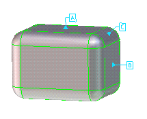
The figure below shows a part with primary, secondary, and tertiary datums attached.
Creating GD&T datum symbols
When you create a datum on the model, a label is generated which displays the datum identifier enclosed in a box. This label is connected to the datum on the model with a leader line terminating in a solid triangle at the point of contact. The datum label and line are colored green (by default) when the datum refers to a single part, and magenta (by default) when it has been created on an assembly.
You can view the datum symbols that have already been applied to a model in the Structure Browser, as you would other custom process features.
You use the Datums dialog box to add a datum to a model as a point of reference. To access the dialog box, double-click the Datum symbol in the Template Browser. The Datums dialog box contains the following options:
Elements:
Specify the feature or list of features to be referenced by the datum definition. A feature can be a face, a functional feature, or an existing tolerance on which the datum will be constructed. Any single feature is valid. To specify a list of features, each feature must be of the same class. If the first feature specified is a cylinder, then the remaining features must also be axial features because a pattern is assumed from the list. To specify a stepped datum, select multiple planar features which have the same surface normals.
Docuplane/Free:
Specify whether the datum should be free or placed on a docuplane. If the latter, specify the Docuplane by clicking it or by selecting it from the browser. Note that the docuplane implies the owner of the datum; the owner of its docuplane set becomes the owner of the datum. Therefore the Owner box is inactive when a docuplane is selected.
Owner:
To select features over multiple parts of one assembly, first specify the assembly in the Owner field, and then specify the features with Elements. When the features are specified first, this field is used to display the name of the owning part of the selected features.
Datum Type:
This box indicates the type of datum, for example, "Plane" or "Axis".
Fix Text:
You can include additional fix text by clicking Fix Text to expand the dialog box and display the boxes in which to add a Prefix, Postfix, Superfix, and Subfix. Clicking the buttons opens the Dimension Presets table in which you can select predefined fix texts.
Identifier:
Enter a valid identifier for the datum. This is usually a capital letter, excluding I, O, and Q. If the identifier entered is invalid, or has already been used, an error message is displayed. The identifier automatically defaults to the next available valid letter.
Dtm Targets:
Select feature points to be datum targets for the datum. (The selected feature points become datum targets when you have finished defining the datum.)
To create a datum on a part,
Select the datum feature on the basis of its geometrical relationship to the toleranced feature and the requirements of the design.
1. Click 3D Documentation and then, in the Annotate group, click Symbol.
2. Click to expand the GD&T category in the template browser and double-click Datum. The Datums dialog box opens.
3. To specify features over a single part: Specify the desired elements of the model to which you want to attach a datum symbol. The owner of the elements is displayed in the Owner box.
4. To specify features over multiple parts of one assembly: Specify the assembly name in the Owner box, and then specify the elements.
5. Specify whether the datum should be attached to a docuplane or remain free. (The Owner field is deactivated when a docuplane is selected, as the datum owner is taken to be the docuplane owner.)
6. Specify any additional fix text by clicking Fix Text to expand the dialog box and display the text fields.
7. Specify the datum identifier. Creo Elements/Direct Modeling provides the next available valid letter by default, but you can change this if necessary. Do not use the letters I, O, or Q.
 Symbol.
 to attach the defined datum.