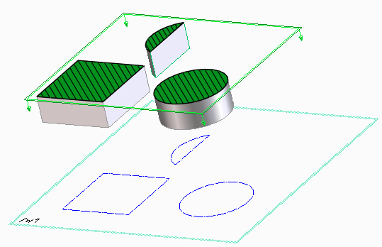
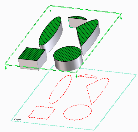
Clip lines are displayed at the intersection of model faces and defined clipping planes.
The different areas in the preceding image are:
1. Active workplane
The clip lines are projected on to this active workplane.
2. Clip lines
The lines displayed at the intersection of model face and defined clipping plane. The clip lines are projected on to the active workplane as blue lines.
3. Clipping plane
The clipping plane intersects with the model.
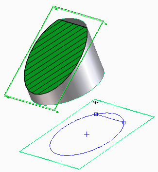
You can use the projected lines as reference to draw 2D geometry using the 2D CoPilot commands. The following example shows you how to draw a line relative to a projected clip line.
To draw a line relative to a projected clip line,
1. Click Modeling and then, in the Draw group, click a 2D CoPilot command such as Line/Arc.
2. Move the cursor over a clip line at the intersection of a face and a clipping plane. The clip line is projected on to the active workplane as a blue line.
3. Click any point on the projected clip line.
4. Move the cursor away from the projected clip line. The visual feedback shows the distance of the cursor from the projected clip line.
5. Click any point on the workplane at a desired distance from the projected line to complete the line.
You can also use other 2D CoPilot commands and options such as Measure Relative to draw lines, arcs, or circles relative to the projected clip lines.
When you start a 2D CoPilot command, the 2D CoPilot performs one of the following actions depending on the 3D geometry in the viewport:
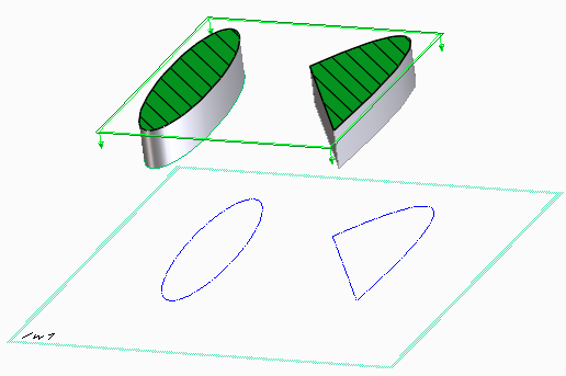
• Projects a straight line, circle, or an arc clip line onto an active parallel workplane.
• Projects an ellipse and a spline clip line onto an active parallel workplane.
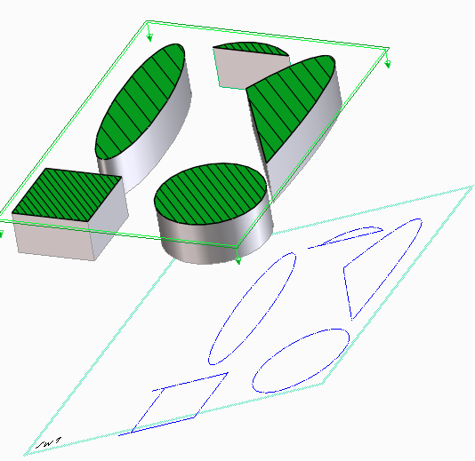
• Projects a straight line, a circle, an arc, an ellipse, and a spline clip line onto an active non-parallel workplane.
• Projects intersecting clip lines onto an active workplane.
 Line/Arc.