The 3D object settings control the default colors, size, border, grid, and resolution of all new workplanes you create. To change the properties of an existing workplane, see the
Workplane properties. You can set the minimum size for new workplanes. The workplane will grow as you add profiles or construction geometry. If you create a new workplane without specifying a position, the lower left corner of a new workplane is positioned at 0,0 minus 10% of the default size. For example, if the default size is 100, then the lower left corner of the workplane is positioned at -10,-10.
You can also change the default appearance, resolution, and other settings for new parts. With the exception of the Visual clipping section, these settings control the characteristics of new parts, but have no effect on existing parts. If you want to change an existing part's settings, see
Set part properties.
If you change display settings for a part, you may need to enable Mixed mode in Show Settings to see your changes.
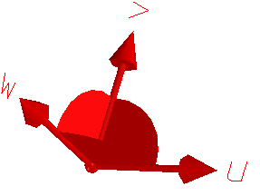
The 3D object settings also control the appearance and visibility of the coordinate system graphical representation, which is shown below. You can change these settings to make the coordinate system easier to see.
To change the default 3D object settings,
1. Click File > Settings > 3D Object. The 3D-Object Settings dialog box opens. The left pane of the 3D-Object Settings dialog box lists the categories of options and the right pane displays the options for each category.
2. Set the following Part Appearance settings for new parts:
◦ Part Base Color: The base color of parts.
◦ Part Edge Color: The color of the edges on parts. The default is the part color. The edge color is not displayed when you render a model.
◦ Part Face Color: The default color of face parts.
◦ Current Part Color: The edge color of the active part.
◦ Lightweight Edge Color: The part color when you load a part as a lightweight model.
◦ Reflectance Color: The color of reflected lights for parts.
◦ Reflectance Power: The amount of reflectance for parts.
◦ Mirror Power: The default value of Mirror Power for the new part. Mirror Power is the strength of reflection of the environment map on the models surface. See
Display objects with shadows and mirror. If the default value is None, the Global Mirror Power value is used. For Global Mirror Power, see
Change viewport settings.
◦ Part Transparency: The default transparency of parts.
3. Set the following miscellaneous settings for new parts (Part Misc):
◦ Density: The default density of parts.
◦ You can set the following modes, which control how new parts are displayed:
▪ Shaded: Display new parts as solid, shaded models.
▪ Edged: Show part edges through the solid.
▪ Wire: Display parts as wireframe models.
▪ Hidden: Display facets and edges of parts inside or behind other parts.
▪ Hidden Dimmed: Display parts with hidden edges and facets dimmed.
◦ Graphical Resolution: The graphical resolution of parts. Drag the slider to change the graphical resolution.
4. Set the following Part Load settings for lightweight models and partially loaded parts:
◦ Lightweight:
▪ Without Edges: Display lightweight models without edges.
▪ Without Vertices & Labels: Display lightweight models without vertices and labels.
5. Set the following Resolution for parts and workplanes:
◦ Part: The geometric resolution of parts. You can specify any value between 1.0E-1 to 1.0E-6. The coarsest recommended value is 1.0E-2 mm.
When you change the default part resolution, you can choose to set the default workplane resolution to the same value.
◦ Workplane: The geometric resolution of workplanes. You can specify any value between 1.0E-1 to 1.0E-6, but the coarsest recommended value is 1.0E-2 mm.
6. Set the following appearance settings for the workplane (Workplane Appearance):
◦ Border Type: The type of border. Outline displays a wide frame around the visible workplane. Full displays the entire visible workplane in the front and back border color.
◦ Transparency: The transparency of the workplane.
◦ Border Font: The default border font.
◦ Border Color (Front): The color border in front of the workplane.
◦ Border Color (Back): The color of the rear border of the workplane.
◦ Current Border (Front): The color of the border in front of the workplane when the workplane is active.
◦ Current Border (Back): The color of the rear border when the workplane is active.
◦ 2D Color (Geometry): The color of the profile geometry on the workplane.
◦ 2D Color (Construction): The color of the construction geometry on the workplane.
◦ Line Type (Geometry): The line type for the geometry lines (profile geometry) on the workplane. The default line type for the geometry lines is a solid line type.
◦ Line Type (Construction): The line type for the construction lines (construction geometry) on the workplane. The default line type for the construction lines is a dotted line type.
7. Set the following settings for the Workplane Grid:
◦ Mode: The style of the workplane grid.
◦ Color: The grid color.
◦ Spacing: The width and height of the workplane grid.
8. Set the following miscellaneous workplane settings (Workplane Misc):
◦ Set the Minimum Size for new workplanes. You can choose from the list of values or type your own.
◦ Set the New On Face (& Project) for new workplanes. You can choose:
▪ Up Dir along Z-Axis: Positions the new workplane on the face with the default size and with the up direction oriented with the global Z axis.
▪ According to Face Geo: Positions and sizes the new workplane according to the face.
9. Set the following settings for Coordinate Systems:
◦ Select a Color for the graphical representation.
◦ Type a Size for the graphical representation.
◦ Select Store Visibility if you want your coordinate system's visibility stored with its owner. This makes the coordinate system visible when the part or assembly file is loaded, even when viewport settings are set to hide coordinate systems.
◦ Type a character in the U Axis Label box as the label for the u-axis.
◦ Type a character in the V Axis Label box as the label for the v-axis.
◦ Type a character in the W Axis Label box as the label for the w-axis.
• The default axis labels are u, v and w. You can use up to four characters for the axis labels. If you change the u, v, or w-axis labels, the updated labels are assigned as default labels for all subsequently-created coordinate systems.
• If you open a coordinate system created using Creo Elements/Direct Modeling 19.0 or later in earlier versions of Creo Elements/Direct Modeling, the default axis labels for the earlier versions are displayed in the viewport.
• If you open a coordinate system created using Creo Elements/Direct Modeling 18.1 or earlier versions in Creo Elements/Direct Modeling, the default axis labels for the current Creo Elements/Direct Modeling version are displayed in the viewport.
10. Click Reset to restore the settings of a single category, selected categories, or all categories of options to the Site, Corp, or Factory default settings. The Reset 3D-Object Settings dialog box opens. The current category is selected by default if you click Reset.
11. Click Close to close the dialog box. Changes are applied as you change settings.
 3D Object. The 3D-Object Settings dialog box opens. The left pane of the 3D-Object Settings dialog box lists the categories of options and the right pane displays the options for each category.