With Compare Parts, you can compare the geometry of two nearly identical parts.
This option helps you compare different versions of a model. For example, a company might construct a part and send it to a partner for finalization. The partner modifies the part and sends it back. With Compare Parts, the differences between the first and second versions can be analyzed, displayed, and kept for further modeling operations.
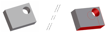
Creo Elements/Direct Modeling highlights the differences:
To compare parts,
1. Load both parts you want to compare in the viewport.
2. Click Analysis and then, in the Verify group, click Compare Parts. The Compare Parts dialog box opens.
3. Select the original or Reference part in the Structure Browser.
4. Select the same face on the changed or Check part.
5. If you want, you can define the accuracy to be used for the part comparison. The lowest resolution of both parts is selected by default. You can choose a lower resolution if you want a rougher comparison of the parts.
6. Creo Elements/Direct Modeling needs to know how to match the parts so they must be aligned in the same position. Choose an alignment option:
◦ No Align: The parts are already aligned.
◦ Auto Align: Creo Elements/Direct Modeling positions the Check part so the selected faces of the Reference part and Check part are aligned. If more than one alignment is possible, you can choose from a list of available alignments using the Next and Previous buttons.
◦ Auto Align with Vertices: If an automatic alignment is not possible, you can select a vertex on the selected Reference part face and the matching vertex on the Check part face. Creo Elements/Direct Modeling positions the Check part so the two vertices are aligned.
◦ Manual Align: If automatic alignment (with or without vertices) is not possible, you can position the Check part using the dynamic position dialog. You can also use the Mate Align options for manual alignment.
7. Click Calculate. Creo Elements/Direct Modeling displays the Reference part and the Check part in separate viewports. The differing faces, edges, and vertices are highlighted in different colors.
Limitations
• Compare parts only compares geometric and topologic information. It doesn't include any other information such as blends or other feature data in the comparison.
• Scaled parts may not compare accurately. The farther geometry is from the reference points (the points at which the parts align), the more likely the comparison will fail and produce Only Ref or Only Check results.
• The comparison method for edges and faces is based on a smart sampling technique. Because it samples a finite (but representative) number of points, the distance returned by Advanced Analysis is an approximation.
Two elements are geometrically equal within a given accuracy if one element contains the other: Element e1 contains element e2 within a given accuracy if the distance from each 3D point sampled from element e1 to e2 is smaller than the given accuracy. When the accuracy value changes to a value greater than the returned distance, Creo Elements/Direct Modeling treats the two elements as if geometrically equal (although they may not be).
 Compare Parts. The Compare Parts dialog box opens.