As you create more and more parts, and as their relationships become more complex, you need an easy way of organizing those parts into a logical structure. In its simplest form, an assembly structure contains parts and assemblies arranged together in logical groups.
You can create parts and assemblies by giving each one a name and an owner. Creo Elements/Direct Modeling provides a default name and root (/) as the default owner.
Once you know how you want the parts to be structured and named, you can take over the responsibility from Creo Elements/Direct Modeling and name each part exactly what you want and place it in exactly the right position. Later you can always rename and move parts and assemblies in your tree structure.
You will not be able to reload an assembly file into Creo Elements/Direct Modeling if one of its constituent part files has been renamed.
Understanding parts and assemblies
Assembly structures are made up of "parts" and "assemblies" and define which parts belong to which assemblies. It is important for you to understand the contents of parts and assemblies in order to use them effectively.
A part is the basic component in the assembly structure. It is described by the following information:
• Part name
• Location
• Geometry
An assembly can be considered as a 3D object which can combine several parts and structure them in a hierarchy. It contains the following information:
• Assembly name
• Location
• Structure
• References to parts or other assemblies
A container is a special type of assembly. A container can be used to store all kinds of tools necessary for the creation of a part. It contains the following information:
• Parts
• Assemblies
• Workplanes
• Workplanesets
• Tool bodies
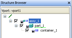
An assembly (1), a part (2), and a container (3)
Viewing an assembly structure
Assembly structures can be viewed graphically with the Structure browser. This browser shows all assemblies, parts, workplanes, workplane sets, view sets, features and other assembly elements as icons. The assembly tree can be collapsed or expanded, and made to show only specific levels of the assembly. In a separate list, details such as Model Names can also be displayed. This information can be sorted and filtered, and object names and Model Names can also be edited.
Allowed parcel names
In many places, name checks (such as for part names) allow a wide range of characters. Because of their special role in file systems and shells, the following characters are invalid for parcel names:
: * ? < > | [ ] \ / ' " ; = + % $& ~ ! # @ ^ ,
• Maximum name length is 240 characters.
• Maximum path length is 1000 characters. Paths consist of the concatenation of the name with all levels above it, separated by /, for example, /a1/a2/a3/p1.
• You may only use ASCII values for variables used in relations.