1. Click Analysis and then, in the Verify group, click the arrow next to Clash/Clearance.
2. Click Clash. The Clash dialog box opens.
3. Click List vs. List.
4. Click 1st Parts and identify the first part.
5. Click 2nd Parts and identify the second part.
6. Under Results select "All," "Clashing Only," or "Touching Only"
7. Click View.
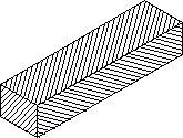
Creo Elements/Direct Modeling displays a viewport showing the parts that are clashing (in red) or touching (in yellow). In Figure 175 these are represented by hatched areas and dashed lines respectively.
An output window is also displayed giving the following information if "Clashing Only" is selected or if "All" is selected and there are no touching parts:
==>CLASH RESULTS<= = "/p1" clashes with "/p2"=> "/clash/p1_p2" "/p2" clashes with "/p1"=> "/clash/p1_p2"
To close the output window, click Close. To close the temporary viewport, click OK. If "All" or "Touching Only" are selected, the output window will provide similar information as above for the results, identifying where any clashing and/or touching has occurred.
If you specify Keep Reslt, Creo Elements/Direct Modeling creates a separate part out of the interference volume or touching area and adds it to the parts browser. The information on clashing or touching objects can then be turned on or off, or deleted separately.
When the Keep Reslt button is set the displayed yellow (touching) and red (clashing) parts are kept in the object tree which is visible in the structure or parts browser. This means that the parts (volume model for clash and sheet area for touching) are not deleted from the command. The result is a new assembly called "Clash." To see the clashing result, a new assembly called "Clashing" is created under "Clash: and the parts are put under this title. To see the touching result, a new assembly called "Touching" is created under "Clash" and the parts are put under this title.
If the user selects either the "Clashing Only" or "Touching Only" option, the program removes the other subassembly and only the wanted results are left over; again these are visible in the structure browser.
Press fit parts clash intentionally. You can switch Press Fit off to see the results of clashing press fit parts.
Library parts such as screws, also clash intentionally. You can switch 3D Lib and/or Thread off to see the results of clashing such library parts.
Specifying the option All in List, tells Creo Elements/Direct Modeling to consider a list of parts, an assembly, parts in an assembly, or parts and an assembly.
The parts generated from touching areas are double-sided non-manifold shells, that is, non-manifold shells having opposing normals on both sides. In subsequent modeling operations, they behave like any non-manifold solid.
 Clash/Clearance.