Reference Topics > Example: Move a face using a line between two points
Example: Move a face using a line between two points
You can move faces or features using 2D elements such as linear bisector, angular bisector, or lines between two points.
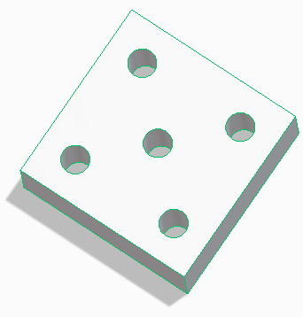
In the following example, to move a hole (cylindrical face), you can use the Line Between 2 Points command to draw lines between the centers of other holes and then use the midpoints of the lines as references.
To move the cylindrical hole using a line between two points,
1. Select the internal cylindrical face that you want to move and click on the Command Mini Toolbar (CMT). A 3D CoPilot appears at the selected point.
2. Select the circular plane of the 3D CoPilot as shown in the image below. A planar dragger with an orange boundary is created.
3. Press M, or right-click in the viewport and choose Line Between 2 Points on the context menu.
Alternatively, press SPACEBAR or the assigned key and click on the Option Mini Toolbar (OMT).
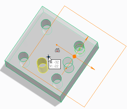
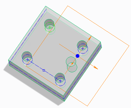
4. Select the center of the first hole as shown below. As you move the cursor over the hole, the visual feedback displays the center of the hole.
5. Similarly select the center of the second hole to draw the line between the two centers.
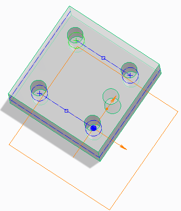
6. Similarly, press M and create a line between the other two holes as shown below.
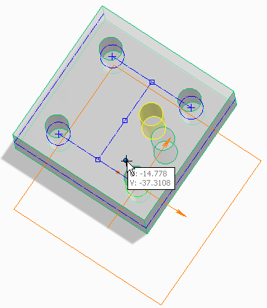
7. You can then press M and draw a line between the midpoints of the two lines as shown.
8. Finally, move the cursor and use the midpoint of the line to place the hole.
 on the Command Mini Toolbar (CMT). A 3D CoPilot appears at the selected point.
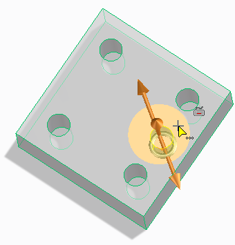
 on the Option Mini Toolbar (OMT).
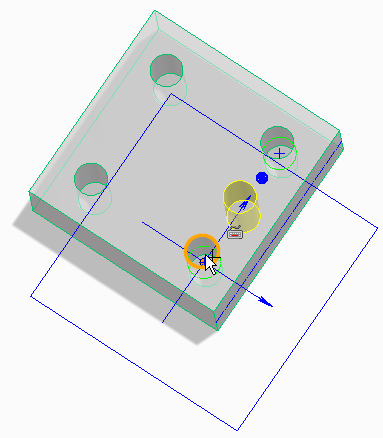
 to complete the operation.