Every point, vector, and direction in Creo Elements/Direct Modeling is identified by three coordinates, one for each 3D axis.
Creo Elements/Direct Modeling uses two different 3D coordinate systems: global (X-Y-Z) and local (U-V-W).
If you create a new workplane in the default position, its local origin (0,0) is the same as the global origin (0,0,0). U is the same as the X direction, V is the Y direction, and W is the Z direction. If you reposition the workplane, its U, V, and W axes can change direction.
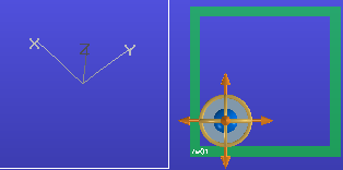
Here you can see the global X-Y-Z axes which are displayed in the top left corner of the viewport when you position an object. The 3D CoPilot is oriented in the U-V-W directions, which are relative to the object:
As you can see, these axes may be different. The global axes will never change, but the axes for the workplane can.