You can project outlines from 3D geometry onto the active workplane to create new 2D geometry. This is useful when you need to create a new part based on an outline or dimensions from an existing 3D part.
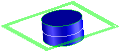
In this example, we projected a cross section, shown as the white line across the middle of the cylinder. Now we can easily make another part with the same diameter. We could have created the same 2D geometry by projecting the top face or edge of the blue part.
To create 2D geometry from 3D geometry,
1. Click Modeling and then, in the Draw group, click the arrow next to Project.
2. Select one of the following under Project Construction or Project Geometry:
Project Construction
◦ Face — Projects the geometry of a face normal to the target active workplane as construction geometry.
◦ 3D Edge — Projects the geometry of a 3D edge normal to the target active workplane as construction geometry.
◦ 2D Edge — Projects the geometry of a 2D edge normal to the target active workplane as construction geometry.
◦ General — Projects the 2D and 3D geometry as defined by the Direction 3D CoPilot as construction geometry.
1. By Target: Projects the geometry normal to the target workplane as construction geometry.
2. By Source: Projects the geometry normal to the source workplane as construction geometry.
3. Free: Projects the geometry as defined by the Direction 3D tool as construction geometry.
◦ Cross Sect — Projects a cross section of the selected part or geometry onto the workplane as construction geometry.
◦ Outline — Projects the outline of parts or faces onto the workplane as construction geometry.
Project Geometry
◦ Face — Projects the geometry of a face normal to the target active workplane as real geometry.
◦ 3D Edge — Projects the geometry of a 3D edge normal to the target active workplane as real geometry.
◦ 2D Edge — Projects the geometry of a 2D edge normal to the target active workplane as real geometry.
◦ General — Projects the 2D and 3D geometry as defined by the Direction 3D CoPilot.
1. By Target: Projects the geometry normal to the target workplane.
2. By Source: Projects the geometry normal to the source workplane.
3. Free: Projects the geometry as defined by the Direction 3D tool.
◦ Cross Sect — Projects a cross section of the selected part or geometry onto the workplane.
◦ Outline — Projects the outline of parts or faces onto the workplane.
3. Select the edges, faces, or part to be projected.
You can switch between Geometry and Construction modes while projecting 3D geometry by selecting either Geometry or Construction in the Project Direction, Cross Section, or Project Outline dialog box.
4. Click to complete the operation.
To resolve resolution conflicts when projecting a cross section,
The following options define how to resolve part-to-workplane resolution conflicts (they are only active if a conflict exists):
• Switch Res: In the case of an empty workplane, use this option to change the resolution of the workplane to match the resolution of the part. This is the default in this case.
• Re-Intersect: This option can be used in the following situations.
◦ In the case of an empty workplane to avoid changing the resolution of the workplane.
◦ In the case of a resolution mismatch, (that is, the workplane is more accurate than the part and the workplane is not empty. This is the default and the only possible value in the case of a resolution mismatch.
If you have a part of low accuracy (1.0E-3 mm) and are doing a cross section using a workplane of higher accuracy, the system first creates a profile with the accuracy of the part and then tries to resolve the resolution conflicts by re-intersecting the resultant edges.
You may end up with an open contour on the workplane if the re-intersection step cannot find new vertex positions by intersection. For example, a circle almost touches a line tangentially but misses it by 1.0E-3 mm, which is valid for a part of this resolution. However, with a workplane of 1.0E-6 mm accuracy there is no intersection point and therefore, the resulting contour will be an open one.
 Project.
 3D Edge — Projects the geometry of a 3D edge normal to the target active workplane as construction geometry.
 2D Edge — Projects the geometry of a 2D edge normal to the target active workplane as construction geometry.
 General — Projects the 2D and 3D geometry as defined by the Direction 3D CoPilot as construction geometry.
 Cross Sect — Projects a cross section of the selected part or geometry onto the workplane as construction geometry.
 Outline — Projects the outline of parts or faces onto the workplane as construction geometry.
 Face — Projects the geometry of a face normal to the target active workplane as real geometry.
 3D Edge — Projects the geometry of a 3D edge normal to the target active workplane as real geometry.
 2D Edge — Projects the geometry of a 2D edge normal to the target active workplane as real geometry.
 to complete the operation.