With the Wrap on surface command, you can assign 2D elements to a face:
• Add a curve to a surface to create or modify wire parts.
• Imprint curves on a surface to create an edge on that surface.
For example, you can use Wrap on Surface to create a label for a can. First, create the text on a workplane. Then wrap it onto a cylindrical surface.
Use one of two techniques to adjust the 2D element to the parameter area of the surface.
1. Fit: Stretch the edges of the 2D curve so that the boundaries match the size of the face.
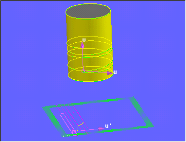
2. Dir: Specify a point on the face (Face Point) and a second point on the workplane of the 2D edge (Edge Point). You can also specify a direction in the workplane (Edge u-dir). This direction is used as the U-axis of the parameter area and will provide the rotation angle for the mapping operation.
To wrap 2D geometry onto a surface,
1. Click 3D Geometry and then, in the 3D Curve group, click More next to Spline 3D.
2. Click Wrap on Surf in the Indirect section. The Wrap on surface dialog box opens.
3. Click Face and specify the face onto which the edges should be mapped.
4. Click Edge and select the 2D source elements.
5. Choose the adjustment method. For example Dir to rotate and place the edges before they are wrapped onto the face.
6. To select a reference point on the face click Face Point.
7. Click Edge Point for the position on the workplane that will match the 3D point on the Face.
8. Use Edge u-dir to specify the U-axis for the edges.
9. Select the method:
◦ Imprint: To imprint the 2D geometry onto the face.
◦ Add Curve: To create a wirepart for the new 3D curve.
10. If necessary, enter a name for the wirepart in the Wirepart data entry field (for example, "/p1")
11. Click to complete the operation.
The Wrap on surface dialog box has the following options:
• Face: The face upon which the curve should be defined. Note that a face with a read-only status is not selectable.
• Edge: The 2D edges that are going to be mapped onto the face. Possible to select numerous edges on the current workplane.
• Adjust: Method to use for adjusting the edges within the parameter range:
◦ Dir when orientation and position of the scope should be adjusted
◦ Fit scales the bounding box of the edges to the size of the range.
• Face Point: A point on the selected face, needed as reference for adjustment.
• Edge Point: This point on the workplane of the edges is exactly mapped into the corresponding reference (Face Point). (Only in Dir mode.)
• Edge u-dir: Direction on the workplane that states the u- axis of the face parameter. The local x- axis of the workplane is used as default. (Only in Dir mode.)
• Add Curve and Imprint: Mode of curve creation
◦ Add Curve to modify an existing wirepart or create a new one.
◦ Imprint when adding edges to the selected face.
• Wirepart: The name of the wirepart that will be used for curve creation. (Only in Add Curve mode.)
• Show Face Box: Displays a feedback on the workplane, showing the parameterized extend of the selected face.
• Use Iso Lengths: Scales the parameter range to achieve "nearly" length preserving results for the mapping operation.
 Spline 3D.
 Wrap on Surf in the Indirect section. The Wrap on surface dialog box opens.
 to complete the operation.