Multiview can help you precisely locate a point in 3D space.
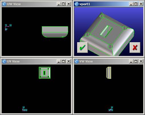
Multiview displays four viewports, as shown in the image below. Three viewports display orthographic views of the model or curve taken along the zero of each axis, and the standard viewport is displayed in the upper right.
You can use the mouse to pan or zoom in the UW, UV, and VW viewports, but you cannot rotate in these views. You can rotate the model or curve in the standard viewport as normal.
Each of the additional viewports contains a view of the part on which you are working, as seen in the planes defined by the U-V axes, the U-W axes, and the V-W axes. The fourth viewport is the standard 3D user view. The standard user view has the same dynamic functions (rotate, zoom, and translation) as the viewport before switching on the multiview.
If you change the origin or the local coordinate system (U, V, W) when modifying a spline curve, the local views are updated automatically. When you start creating 3D curves, Creo Elements/Direct Modeling uses the default local coordinate system which is defined by the global coordinates, that is, with the origin set at the coordinates (0,0,0), and with U=X, V=Y, W=Z.
When used in close combination with the Catch Tool, the multiview provides visual feedback of the position of the cursor so that you can accurately locate points in 3D space.