You can use the commands Line/Arc, Arc 3 Pnts, Arc Center, and Arc Smooth to draw different types of arcs or lines. All commands provide visual feedback to help you draw the arcs or lines.
• When you draw a line or an arc, you can select two points in the viewport or on a workplane to set the line which connects the two points as a mirror. For more information, see
Set a mirror for 2D geometrical elements.
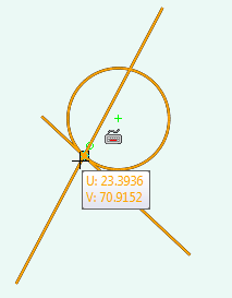
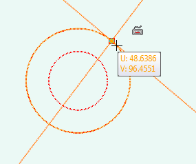
• When you draw 2D elements with 2D CoPilot support, the cursor snaps to intersection points and the intersecting elements are highlighted in the viewport as shown in the following image.
To draw a line or arc,
1. Click Modeling and then, in the Draw group, click Line/Arc.
2. Click a point in the workplane for the start location of the line or arc.
3. Move the cursor. The visual feedback shows a line or an arc. Press B to toggle between a straight line and an arc.
Depending on the
2D CoPilot settings, the visual feedback shows Cartesian Coordinates, Polar Coordinates, or the Cursor Text as you move the cursor in the viewport. To change the feedback,
• Click on the status bar to display Cartesian coordinates. You can:
1. Press TAB, type the Cartesian u coordinate, and press ENTER to set the u coordinate.
2. Type the Cartesian v coordinate and press ENTER to complete the line.
• Click on the status bar to show the polar coordinates. While drawing a line, you can:
1. Press TAB, type the length of the line, and press ENTER to set the length.
2. Type the angle and press ENTER to complete the line.
While drawing an arc, you can:
1. Press TAB, type the radius of the arc, and press ENTER to set the radius.
2. Type the angle of the arc and press ENTER to complete the arc.
While drawing an arc, you can press TAB twice, type the angle, and press ENTER to set the angle of the arc.
• To bend the line, you can also right-click and choose Bend from the context menu. Alternatively, you can press SPACEBAR, click on the Option Mini Toolbar (OMT), and select Bend.
• You can type the radius of the arc and press ENTER to set the radius of the arc.
• You can right-click and choose Set Bend Angle on the context menu to set the bend angle of the arc.
4. Click a point in the workplane for the end location of the line or arc. You can also type the length and press ENTER to complete the line or type the radius of the arc and press ENTER to complete the radius.
When you are creating an arc, if polar coordinates are displayed in the viewport, you can press TAB and type the radius and angle of the arc and press ENTER to complete the arc.
You can use the Linear Bisector or the Angular Bisector command (on-the-fly) when you draw a line or an arc; for example, to locate a point on the bisector of an angle formed by intersection of two lines.
• To use a linear bisector:
◦ Press X or,
◦ Right-click and choose Linear Bisector on the context menu or,
◦ Press SPACEBAR or the assigned key and click on the Option Mini Toolbar (OMT).
• To use an angular bisector:
◦ Press Y or,
◦ Right-click and choose Angular Bisector on the context menu or,
◦ Press SPACEBAR or the assigned key and click on the OMT.
You can use the Line Between 2 Points command (on-the-fly) to create a temporary line and then use the midpoint of this line as a reference to create lines or arcs.
To create a temporary reference line between two points:
a. Press M, or right-click in the viewport and choose Line Between 2 Points on the context menu.
Alternatively, press SPACEBAR or the assigned key and click on the OMT.
1. Click Modeling and then, in the Draw group, click the arrow next to Arc.
2. Click 3 Points.
3. Click the start point of the arc. The 2D Copilot helps you to find a center point, midpoint, vertex, or an intersection point on an element.
You can also type coordinates and press ENTER to enter the start point of the arc.
4. Move the cursor.
Depending on the
2D CoPilot settings, the visual feedback shows the Cartesian coordinates, polar coordinates, or the cursor text as you move the cursor in the viewport. To change the feedback,
• Click on the status bar to show the Cartesian coordinates. You can type the Cartesian coordinates to select the end point of the arc.
• Click on the status bar to show polar coordinates. You can type the Polar coordinates to select the end point of the arc.
5. Click the end point of the arc. You can also type a distance and press ENTER to determine the end point of the arc.
6. Move the cursor between the start and end point. The visual feedback shows an arc between the start and end points.
Depending on the
2D CoPilot settings, the visual feedback shows the Cartesian coordinates, polar coordinates, or the cursor text as you move the cursor in the viewport. To change the feedback,
• Click on the status bar to show the Cartesian coordinates. The Cartesian coordinates are shown from the previous selected point in the viewport. You can:
1. Press TAB, type the Cartesian u coordinate, and press ENTER to set the u coordinate.
2. Type the Cartesian v coordinate and press ENTER to complete the arc.
• Click on the status bar to show polar coordinates. The visual feedback shows the radius and the angle of the arc. You can type the radius of the arc and press ENTER to complete the arc.
• Ensure that Automatic Tangent Circle by 3 Points is selected in
2D CoPilot settings. By default, Automatic Tangent Circle by 3 Points is selected.
• As you move the cursor over other 2D elements in the viewport, the 2D CoPilot automatically shows an arc which is tangent to those elements.
7. Click the third point to complete the arc. The feedback shows you the result before the click. If the third pick is on a geometry element, the arc will be tangential to that element. You can also type a radius and press ENTER to create the arc, which will have the orientation given by the current cursor position.
You can use the Linear Bisector or the Angular Bisector command (on-the-fly) when you draw an arc; for example, to find the midpoint of an arc.
• To use a linear bisector:
◦ Press X or,
◦ Right-click and choose Linear Bisector on the context menu or,
◦ Press SPACEBAR or the assigned key and click on the Option Mini Toolbar (OMT).
• To use an angular bisector:
◦ Press Y or,
◦ Right-click and choose Angular Bisector on the context menu or,
◦ Press SPACEBAR or the assigned key and click on the OMT.
You can use the Line Between 2 Points command (on-the-fly) to create a temporary line and then use the midpoint of this line as a reference to create lines or arcs.
To create a temporary reference line between two points:
a. Press M, or right-click in the viewport and choose Line Between 2 Points on the context menu.
Alternatively, press SPACEBAR or the assigned key and click on the OMT.
8. You can create as many arcs as you want before you close the operation.
9. Click to complete the operation.
To draw a Center arc,
1. Click Modeling and then, in the Draw group, click the arrow next to Arc.
2. Click Center & 2 Points.
3. Click the center of the arc and move the cursor.
Depending on the
2D CoPilot settings, the visual feedback shows the Cartesian coordinates, polar coordinates, or the cursor text as you move the cursor in the viewport. To change the feedback,
• Click on the status bar to show the Cartesian coordinates. You can type the Cartesian coordinates to select the start point of the arc.
• Click on the status bar to show polar coordinates. You can type the Polar coordinates to select the start point of the arc.
4. Click the start point of the arc or enter a radius value and press ENTER to determine the start point in that distance in the given direction.
5. Move the cursor to see the arc. The 2D Copilot shows visual feedback for the angle.
Depending on the
2D CoPilot settings, , the visual feedback shows the Cartesian coordinates, polar coordinates, or the cursor text as you move the cursor in the viewport. To change the feedback,
• Click on the status bar to display Cartesian coordinates.
• Click on the status bar to show the polar coordinates. The visual feedback shows the radius and the angle of the arc. You can, type the angle of the arc, and press ENTER to complete the arc.
6. Click a third point to complete the arc. You can also type an angle and press ENTER to complete the arc.
Type a positive value to orient the angle in the direction of movement of the cursor. Type a negative angle to flip the direction.
You can use the Linear Bisector or the Angular Bisector command (on-the-fly) when you draw an arc; for example, to find the midpoint of an arc.
• To use a linear bisector:
◦ Press X or,
◦ Right-click and choose Linear Bisector on the context menu or,
◦ Press SPACEBAR or the assigned key and click on the Option Mini Toolbar (OMT).
• To use an angular bisector:
◦ Press Y or,
◦ Right-click and choose Angular Bisector on the context menu or,
◦ Press SPACEBAR or the assigned key and click on the OMT.
You can use the Line Between 2 Points command (on-the-fly) to create a temporary line and then use the midpoint of this line as a reference to create lines or arcs.
To create a temporary reference line between two points:
a. Press M, or right-click in the viewport and choose Line Between 2 Points on the context menu.
Alternatively, press SPACEBAR or the assigned key and click on the OMT.
7. You can create as many arcs as you want before you close the operation.
8. Click to complete the operation.
To draw a smooth arc tangential to one or two elements,
1. Click Modeling and then, in the Draw group, click the arrow next to Arc.
2. Click Smooth.
3. Click an existing arc, line, or open spline and move the cursor. The feedback shows an arc tangential to the selected reference geometry. At this stage, you can type the radius of the arc and press ENTER to constrain the arc.
Depending on the
2D CoPilot settings, the visual feedback shows the Cartesian coordinates, polar coordinates, or the cursor text as you move the cursor in the viewport. To change the feedback,
• Click on the status bar to display Cartesian coordinates.
• Click on the status bar to show the polar coordinates. The visual feedback shows the radius and angle of the arc. You can type the radius of the arc and press ENTER to set the radius and constrain the arc.
You can also type the coordinates and press ENTER to pick the end point of the arc.
You can use the Linear Bisector or the Angular Bisector command (on-the-fly) when you draw an arc; for example, to find the midpoint of an arc.
• To use a linear bisector:
◦ Press X or,
◦ Right-click and choose Linear Bisector on the context menu or,
◦ Press SPACEBAR or the assigned key and click on the Option Mini Toolbar (OMT).
• To use an angular bisector:
◦ Press Y or,
◦ Right-click and choose Angular Bisector on the context menu or,
◦ Press SPACEBAR or the assigned key and click on the OMT.
You can use the Line Between 2 Points command (on-the-fly) to create a temporary line and then use the midpoint of this line as a reference to create lines or arcs.
To create a temporary reference line between two points:
a. Press M, or right-click in the viewport and choose Line Between 2 Points on the context menu.
Alternatively, press SPACEBAR or the assigned key and click on the OMT.
• When the 2D CoPilot is active, press SPACEBAR to open the Option Mini Toolbar (OMT) and select Geometry or Construction in the box to change the drawing mode.

 on the status bar to display Cartesian coordinates. You can:
 on the status bar to show the polar coordinates. While drawing a line, you can:
 on the Option Mini Toolbar (OMT).
 on the OMT.
 on the OMT.
 to complete the operation.

