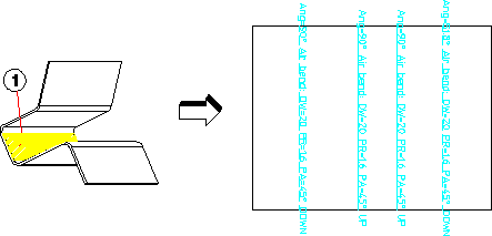

 Dep View.
 Create Flat. The Flat View dialog box opens.
 .
.Both Sides | Click if you want the flat view to account for both sides. | ||
Blind Feats | Click to project blind features to the flat.
| ||
Text File | Click to tell Creo Elements/Direct Annotation to write statistical information into a text file. This additional information includes, among other items, a listing of the bends, the punch and stamp tools used, and the errors which occurred during the unfold. Additionally, the file can be used by other applications and to build customer-specific cost-calculation programs. | ||
by Shop | Click to tell Creo Elements/Direct Annotation to use shop data (which materials, machines, and tools). The specific shop is specified in Creo Elements/Direct Sheet Metal. (The by Shop and K-Factor options under Cylinder Allowance are mutually exclusive.) | ||
K-Factor | The plane in which the length of a curved sheet metal part remains unchanged is identified by the neutral phase. The portions on either side of this neutral phase can become longer or shorter. The location of this neutral phase relative to the material thickness (T) is described in terms of a parameter known as the k-factor. ANSI defines this k-factor as the offset of the neutral phase relative to T, while DIN defines the k-factor as the offset of this neutral phase relative to T/2. The k-factor adopted in this menu meets ANSI standards (0.5 = middle of the sheet). A k-factor under Cone Allowance is independent of the Cylinder Allowance factor. | ||
Radius | This is the radius that is used for the inner radius of sharp bends of the sheet metal design. The outer bend radius is the specified value plus the material thickness. |
All annotations, detail borders, and section lines added to the parent flat view are lost when you create a partial view. This information is not recovered by restoring the full view later. |
You must activate Creo Elements/Direct Sheet Metal to correctly flatten side faces having features. |