A detail view shows a particular area of an existing view to provide greater clarity.
A parent view must already be available before you can create a detail view. The figure shows an example of a parent view (1) and an associated detail view (2).
Creo Elements/Direct Annotation applies the Detail view positioning strategy to Broken views and Partial views.
To create a detail view,
1. Click Annotation and then, in the Setup group, click the arrow next to Dep View.
3. Specify the parent view in one of the following ways:
◦ Type the name and path of the view in the Parent View data entry field.
◦ Click the view in the Creo Elements/Direct Annotation Viewport.
◦ Select the view from the Drawing Browser.
The detail border options are visible under Create Border.
4. Click one of the border types:
◦ Rectangle
◦ Circle
◦ Polygon
◦ Spline (You can define the default border type in Default Setting Browser.)
5. Draw a detail view border on the parent view.
6. Click the first point of the border.
7. Complete the border:
◦ For rectangles and circles, click the other point to define the border.
◦ For polygons and splines, continue clicking points as required. You can click Back to undo the last specified point of the border. When you are finished, click Accept.
To avoid problems, define borders as shown in the image in blue. Avoid following part borders (shown in red).
8. If necessary, type a new detail view number in the Number data entry field.
9. Type a scale factor for the detail view in the Scale data entry field.
10. Accept or change the Profile default setting.
11. To preview the view in a 3D viewport, click Preview.
12. Check Preserve View Center to maintain the position of the detail view when its border is moved.
13. Click to complete the operation.
14. Move the cursor into the Creo Elements/Direct Annotation Viewport.
A boxed view placeholder follows the cursor.
15. Click the view position to fix the placeholder on the sheet.
The update occurs automatically for small assemblies. Large assembly requires manual update.
The following option affects the contents of the cutaway and its parent view:
• Visible Border—the detail view border is displayed in the parent view.
When working with detail views, note the following:
• The detail border is not associated to the 3D model.
• If the parent view is deleted, the detail view is also deleted.
 Dep View.
 Create Detail View. The Detail View dialog box opens.
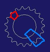
 to complete the operation.