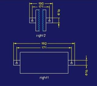
If you have a view of a very long part, you may want to shorten it to display it more clearly on the drawing. You can remove the middle of the part yet retain its correct dimensions by creating a broken view. Whether you change the size of the part or use the Measure tool on a broken view, Creo Elements/Direct Annotation calculates the correct dimensions from the model.
Use the same menu whether you are creating new, or changing existing, broken views.
Creo Elements/Direct Annotation applies the Detail view positioning strategy to Broken views and Partial views.
To create a broken view,
1. Click Annotation and then, in the Setup group, click the arrow next to Dep View.
2. Click Broken View. The Broken View dialog box opens.
3. Specify the view (also a standard or a section or detail view) in one of the following ways:
◦ Click the view in the Creo Elements/Direct Annotation Viewport.
◦ Select the view from the Drawing Browser.
◦ Type the name and path of the view in the View box.
4. Optional: You can copy gaps from existing views.
a. Click Copy From View in the Add Gaps section to copy existing gaps.
b. Select a view in the viewport.
c. Click Copy From View again to collect gaps from another view.
5. Click Horizontal or Vertical under Add Gaps and click a point in the 3D Viewport where you wish to create the break in the view.
6. Adjust the gap in the 3D Viewport to the required size.
7. Click to complete the operation, or continue to add gaps, remove gaps, or make any of the following changes:
◦ Under Modify Gaps,
▪ Click Border to adjust the size of the gap.
▪ Click Position to move the gap.
◦ Under Remove Gaps,
▪ Click Selected and specify the gaps to remove.
▪ Click All to remove all gaps.
▪ Check Real View on Parent to seethe view in the 3D viewport as it would appear on the view.
◦ Under Appearance, you can:
▪ Change the Type of line to be Straight, Jagged, or Wavy.
▪ If you specify a jagged or wavy line, specify the Height and Width of the teeth or waves. The height must be less than or equal to the width, and the Inner Gap must be bigger than the height. Note that Width and Height apply to the control polygon of the wavy line, thus the height of the waves will be less than the height of the teeth of a jagged line with the same specifications.
▪ Specify the size of the gap as shown in the broken view in the Inner Gap field.
8. Click to complete the operation.
Creo Elements/Direct Annotation handles dimensions on broken views, as noted above, based on the 3D model. If you create manual geometry that spans both parts of a broken view, Creo Elements/Direct Annotation does not recognize the manual geometry as part of the 3D model; therefore, dimensions created on the manual geometry will not match the dimensions derived from the 3D view.
You can create an orthogonal section view, a dependent general view, a partial view, a detail view, or a cutaway view from a broken view. You can also create gaps in a view from which a section view, a dependent general view, a partial view, a detail view, or a cutaway view has been created. If you create a gap in a small view, the dependent general views are automatically updated. Larger views require manual update.
Limitations
Creo Elements/Direct Annotation will issue an error message if you attempt to:
• Restore the Full view without first removing the broken view gaps in a partial view.
• Create a broken view from a view created by 3D Process in the Create Drawing section or by the Transfer Docuplane command.
• Create a broken view with transferred 3D Documentation.
• Create a broken view from a view with dimensions or reference lines. If you attempt to do so, Creo Elements/Direct Annotation displays a warning that the creation of the broken view will remove the existing dimensions and reference lines.
• Create a section view with a section line that is not orthogonal to the gap.
 Dep View.
 Broken View. The Broken View dialog box opens.
 to complete the operation, or continue to add gaps, remove gaps, or make any of the following changes: