Creo Elements/Direct Annotation provides several different types of dimensioning that you can use to clarify your drawing:
Single
A single dimension applies to only one linear geometry feature:
To create a single dimension:
1. Click Annotation and then, in the Annotate group, click the arrow next to Linear.
2. Click Single. The Single Dimension dialog box opens.
Chained
Chained dimensions are groups of linear geometry features.
The figure shows examples of chain dimensioning using each of the orientation options.
1. Parallel
2. Horizontal
3. Vertical
4. Para to
5. Perp to
To create a chain dimension:
1. Click Annotation and then, in the Annotate group, click the arrow next to Linear.
2. Click Chain. The Chain Dimension dialog box opens.
Symmetry
The symmetry dimension types are:
• Symmetry Single
Symmetry Single dimensioning is a symmetric form of the normal Single dimensioning.
To create a symmetry single dimension:
1. Click Annotation and then, in the Annotate group, click the arrow next to Linear.
2. Click Sym Single. The Sym Single Dim dialog box opens.
• Symmetry Long
Symmetry Long dimensioning is a symmetric form of the Datum Long dimensioning.
To create a symmetry long dimension:
1. Click Annotation and then, in the Annotate group, click the arrow next to Linear.
2. Click Sym Long. The Sym Long Dim dialog box opens.
The dimensioning options Sym Single and Sym Long create symmetry-style dimensions. The figure shows an example of symmetric dimensioning.
In the drawing, the first dimension point is assumed to be on a symmetry line. No extension line or line terminator is drawn for that element, and the dimension text value is doubled to indicate that the dimension represents both sides of the symmetry line. Drawing 1 shows the unseen half of the geometry.
Datum
Datum Long dimensioning creates dimensions using long base lines. For example, The figure shows a rectangular plate dimensioned using Datum Long and the Parallel to orientation option. The common datum point here is the lower left corner of the plate.
To create a datum long dimension:
1. Click Annotation and then, in the Annotate group, click the arrow next to Linear.
2. Click Datum Long. The Datum Long Dim dialog box opens.
Datum Short dimensioning creates dimensions using short base lines. For example, the figure shows a rectangular plate dimensioned using Datum Short with the Vertical and Horizontal orientation options, with the common datum point again at the lower left corner of the plate.
To create a datum short dimension:
1. Click Annotation and then, in the Annotate group, click the arrow next to Linear.
2. Click Datum Short. The Datum Short Dim dialog box opens.
Coordinate dimensioning creates dimensions without dimension lines. This is useful when the geometry of the part would cause dimension lines to be too close together.
To create a coordinate dimension:
1. Click Annotation and then, in the Annotate group, click the arrow next to Linear.
2. Click Coordinate. The Coordinates Dim dialog box opens.
For example, the figure shows a rectangular plate with three holes dimensioned using Coordinates with the Vertical and Horizontal orientation options and the common datum point at the lower left corner of the plate.
Angle
Creo Elements/Direct Annotation measures angles in the counterclockwise direction; you get the complement angle by specifying points in the opposite direction.
To create an angle dimension:
1. Click Annotation and then, in the Annotate group, click Angular. The Angle Dimension dialog box opens.
Angle dimensioning provides four orientation options:
Item
Description
1
Direct
2
Opposite
3
Adjacent+
4
Adjacent-
Circular
Creo Elements/Direct Annotation can dimension the radius of a circle, arc, BSpline, or fillet (from a 3D blend). The Centerline check box on the Radius Dimension dialog box is available to cause the line of radius to connect to the feature center. You can locate the dimension text either inside or outside the feature. By default, the radius dimension is preceded by the character R.
To create a radius circular dimension:
1. Click Annotation and then, in the Annotate group, click the arrow next to Circular.
2. Click Radius. The Radius Dimension dialog box opens.
If the BSpline is derived from a constant radius 3D blend, the radius dimension value is constant on the periphery of the BSpline. You can also dimension any other BSpline at a selected point. In that case the radius dimension value may vary along the BSpline.
The following figures show examples of an arc and a fillet with a radius dimension that has an extension arc. The examples utilize each option: Centerline on is shown on the left, Centerline off is shown on the right.
The following figure shows an example of a fillet.
Creo Elements/Direct Annotation can dimension the diameter of a circle, arc, or fillet (from a 3D blend). The option Centerline on the Diameter Dim dialog box is available to cause the line of radius to connect to the feature center. You can locate the dimension text either inside or outside the diameter.
To create a diameter dimension:
1. Click Annotation and then, in the Annotate group, click the arrow next to Circular.
2. Click Diameter. The Diameter Dim dialog box opens.
The figures show examples of an arc and a fillet with a diameter dimension that has an extension arc. The examples utilize each option: Centerline on is shown on the left, Centerline off is shown on the right.
The following figure shows an example of a fillet.
The Tangential Mode option on the Diameter Dim dialog box allows you to measure the tangential span between circular geometry having a common center. (To dimension tangential geometry not sharing a common center, use Tangential dimensioning.)
The figure shows a view of a cropped cylinder that has been dimensioned in different ways:
• View 1 shows diameter dimensioning with the Tangential Mode option switched on.
• View 2 shows single dimensioning, which does not catch to the tangents.
• View 3 shows diametric dimensioning with Tangential Mode switched off, and radial dimensioning.
Creo Elements/Direct Annotation can measure the length or angle of a major or minor arc. When dimensioning arcs singly, you determine which measurement is used by selecting either the begin or end point of the arc first. Creo Elements/Direct Annotation measures arcs in the counterclockwise direction. You can also measure the length or angle between two different arcs with same center and radius.
To create an arc dimension:
1. Click Annotation and then, in the Annotate group, click the arrow next to Circular.
2. Click Arc. The Arc Dimension dialog box opens.
You can locate the dimension either inside or outside the arc.
The figure shows two possible results using the Arc option. The arc end points are marked in the order they were specified.
Tangential
Tangential dimensions are useful for dimensioning geometry where vertices are not available, and would have to be added manually.
To create a tangential dimension:
1. Click Annotation and then, in the Annotate group, click the arrow next to Circular.
2. Click Tangential. The Tangential Dim dialog box opens.
The figure shows a turned part dimensioned tangentially in the extremum direction (see below).
Chamfer
This feature is required in certain countries to meet recognized design standards. By default, the chamfer dimension is preceded by the angle.
To create a chamfer dimension:
1. Click Annotation and then, in the Annotate group, click the arrow next to Linear.
2. Click Chamfer. The Chamfer Dim dialog box opens.
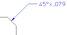
The figure shows an example of chamfer dimensioning.
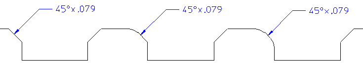
Only chamfers with an angle of 45 degrees can be dimensioned. Chamfers in which one or both of the chamfer-face edges have been blended can also be dimensioned, as shown below:
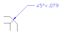
You can dimension a split chamfer which is generated by updating the views of a 3D model and which has multiple lines as shown below:
If you stretch a chamfer or its reference geometry, the chamfer reference geometry is updated. However, the chamfer dimensions are not updated. The chamfer dimensions are not visible after you stretch the chamfer.
 Linear.
 Chain. The Chain Dimension dialog box opens.
 Sym Single. The Sym Single Dim dialog box opens.
 Sym Long. The Sym Long Dim dialog box opens.
 Datum Long. The Datum Long Dim dialog box opens.
 Datum Short. The Datum Short Dim dialog box opens.
 Coordinate. The Coordinates Dim dialog box opens.
 Angular. The Angle Dimension dialog box opens.
 Circular.
 Diameter. The Diameter Dim dialog box opens.
 Arc. The Arc Dimension dialog box opens.
 Tangential. The Tangential Dim dialog box opens.
 Chamfer. The Chamfer Dim dialog box opens.