What is Masterdata?
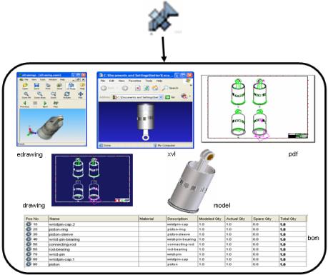
Masterdata is a collection of models, drawings, viewables (eDrawings and XVL), specification documents, pdf files, and other related engineering documents that define and describe a complete manufactured part, including the list of other Masterdata required to produce the BOM.
Masterdata has three primary functions:
1. Provides the representation of the physical part, including its official part number and other attributes such as material. (The Masterdata part number may be different from the model and drawing number and name.)
2. Serves as a container to group and link all supporting documents, including models and drawings.
3. Links all parts together to create a Bill of Materials (BOM) for manufacturing.
Masterdata overview
Creo Elements/Direct Drawing Manager automatically creates Masterdata when you save an assembly, part, or drawing in Creo Elements/Direct Drawing Manager. You can manually create more than one Masterdata.
Creo Elements/Direct Drawing Manager does not create Masterdata when saving containers or workplanes from Creo Elements/Direct Modeling.
Below is an assembly  and its parts
  , each with Masterdata.
  represents Masterdata for an assembly.
  represents Masterdata for each part of an assembly.
and its parts 
Masterdata organizes its design data in a hierarchical structure.
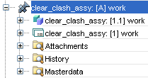
• Models and drawings are listed underneath the Masterdata and can have many revisions and change notes.
• Other documents such as specifications, viewables, and pdf files are also listed underneath the Masterdata and are kept in the Attachments folder.
• The History folder lists previous revisions of models, drawings, and Masterdata.
• The Masterdata folder lists the Bill of Materials components necessary to produce the manufactured part.
The benefits of Masterdata
Masterdata is helpful when a model or drawing represents more than one part, and one document may need to be linked to more than one part.
In an assembly, you may have two parts with the same geometry, but with other characteristics that are different, such as color or material. You do not need to save the geometry in the database twice. Instead, save the geometry once, then link it to the Masterdata for both parts. Also link other documents such as specifications and viewables to each Masterdata.
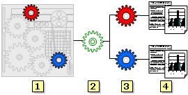
An assembly (1) contains at least one model or drawing. In the example above, the model or drawing is represented by the green cog (2).
The model or drawing is linked to two masterdata records (3): one for the blue part and one for the red part. They share the same geometry, so only one drawing or model is needed. However, the color of the plastic used to mold the parts is different, so the parts are different.
Each part has its own supporting documentation (4). These documents can be in any format, including spreadsheets and text documents.
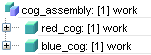
When the assembly is initially saved, it will be displayed in the Recent List like this:
If you have a BOM Editor license, you can scan a BOM and create links between Masterdata.
Masterdata and BOM
Use Masterdata to create a Bill of Materials (BOM) with the Scan BOM command.
Scanning a BOM creates a detailed structure of all the Masterdata linked together, similar to an assembly structure. The dotted lines below represent how a Bill of Materials (BOM) links all Masterdata together and creates a structured list of the assembly. The Masterdata for all the parts of the assembly are linked.
After you scan a BOM for the cog example above, you would see this:
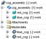
Recent List displays one assembly, two parts, and three Masterdata. The Masterdata for the top level assembly is always displayed at the top of the structure.
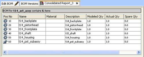
After you scan and create a BOM, you can create a BOM report. The consolidated BOM report below illustrates all the Masterdata for an assembly linked together.