Example: Slotted Plate
Suppose you want to create an engineering drawing from a sketch made at a design meeting. With the copilot functionality, you can quickly turn a sketch into an engineering design without the need for unnecessary construction geometry.
Design Sketch
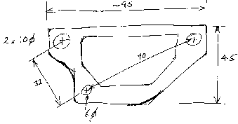
Design Reality
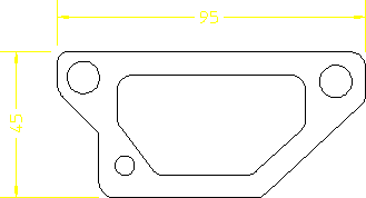
The following example illustrates how to construct the plate with the minimum of construction geometry. As you draw, you will notice that line colors may change as you intersect with existing geometry and the status line gives feedback on your current activity. During certain actions, Creo Elements/Direct Drafting displays negative values. Ignore these for this example.
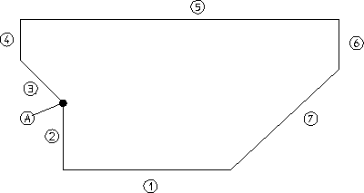
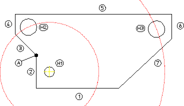
1. Pick Horizontal and draw a horizontal line of length 50 mm (line 1 in the following figure: Slotted Plate - 1)
2. Pick Vertical and draw a vertical line of length 20 mm (line 2)
3. Pick Ang & Len and pick identify point A
4. Move the cursor in an arc and pick an angle of 135°
5. Drag the cursor and pick a length of 18 mm
6. Pick parallel construction line and pick line 1
7. Drag the cursor vertically and pick a point at 45
8. Pick Vertical and draw line 4 to meet the construction line
9. Pick Horizontal and draw a horizontal line of length 95 mm
10. Pick Vertical and draw a vertical line of length 15 (line 6)
11. Pick 2 Pts and draw line 7
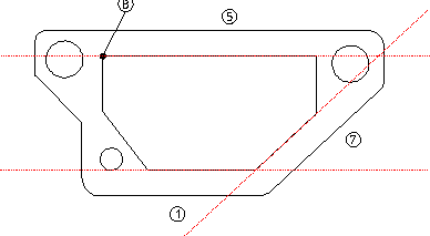
The next step is to construct the holes. The hole at H1 is to be offset at 10 and 8 with diameter 6 mm. Holes H2 and H3 constructed on arcs 32 and 70 mm from H1.
1. Pick Cen & Pt/R (See the following figure: Slotted Plate - 2)
2. Pick OFFSET
3. Pick line 1 and then line 2
4. Define the center point at 8 (x-axis) and 10 (y-axis)
5. Drag the cursor and pick a radius of 3
6. Draw construction circles at 32 and 70 with H1 as the center (center and radius in CONSTRUCT)
7. Pick Cen & Pt/R and construct holes H2 and H3 having radius 5 (precise position is not important)
8. Delete the circular construction geometry.
Slotted Plate - 1
Slotted Plate - 2
The slot can be drawn freehand using the Polygon command. The only criteria is that the inside edge is parallel to line 7.
1. Pick parallel construction lines in CONSTRUCT and draw the parallel lines at a distance of 7 from lines 1, 5, and 7.
2. Pick Polygon and draw the slot starting at point B moving anticlockwise.
Finally, to cleanup the drawing, delete the construction geometry and add some fillets to the corners (FILLET in CREATE 2, size 5 mm).
Slotted Plate - 3