Load the Drawing
1. Click >  Open to open the Creo Elements/Direct Drafting File Browser.
Open to open the Creo Elements/Direct Drafting File Browser.2. Double–click the pd_demos directory.
3. Select the demopart05.mi file and click Open.
4. Click Parametric and then, in the Modify group, click  Zone.
Zone.
Zone.5. Click  Add Multiple.
Add Multiple.6. Type ALL in the user input line and press ENTER.
7. Click  OK.
OK.
OK.Demopart05
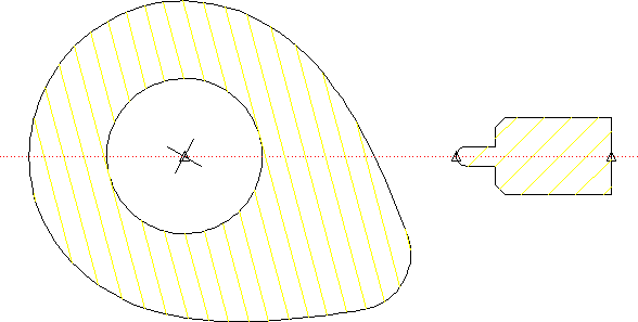
The goal of this example is to force the follower to stay in contact with the cam profile as the cam rotates. By setting up both the cam and the follower as rigid bodies, we dramatically reduce the number of constraints needed to implement this action, and can concentrate more on interaction between the two pieces.
The demopart05.mi model is fairly simple. The only elements in the drawing that are needed specifically for parametrics are the construction line and the three point elements, which are used to facilitate placement of several Point on constraints.