Adding New Geometry
It is often useful as you work with a constrained part to be able to add or delete geometry. Many parametric design systems do not allow this, but Parametric Design handles this situation easily. In the final section of this example, we'll add a new feature to our triangular plate to illustrate how new geometry is integrated into a constrained part.
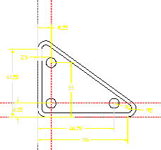
First, let's modify the triangular plate by adding a small "lip" to the outside edge. Use the Creo Elements/Direct Drafting  Equidistance button to create a contour that is 2.5 mm inside the edge of the plate. Dimension the width of this new lip as shown in the following figure.
Equidistance button to create a contour that is 2.5 mm inside the edge of the plate. Dimension the width of this new lip as shown in the following figure.New Geometry on Demopart01
To incorporate this new feature into the Parametric Design constraint system, you only need to click Complete in the Current Constraints dialog box again. Clicking Complete generates the additional constraints needed for the new geometry. Subsequent use of the Solve group buttons recognizes the new feature:
1. After adding new geometry, click Parametric and then, in the Create group, click  Constraints.
Constraints.The Generate Constraints dialog box opens.
2. Click Complete.
3. In the Generate Constraints dialog box, click Show in the Action area.
4. In the Act On box, select New.
5. In the Type box, select All Types.
6. Click Apply to see how the new geometry was constrained.
7. In some cases, the addition of new geometry adds information to the part that causes existing constraints to become unnecessary. Complete will indicate if it finds unused constraints. If applicable, display these constraints with Show, Unused, All Types and Free them if you wish.
8. Change the value of the base dimension to 48.
9. Use  No Keep in the Solve group on the Parametric tab to generate the variation.
No Keep in the Solve group on the Parametric tab to generate the variation.The new lip adjusts along with the rest of the part. |