Hands-On Workshop Tutorial
Introduction to Pro/ENGINEER Wildfire 2.0
Before you get started
This tutorial is intended to be used alongside Pro/ENGINEER Wildfire 2.0.
- Please make sure that Pro/ENGINEER Wildfire 2.0 is installed on your machine before continuing.
- If Pro/ENGINEER is already running, please exit it now.
You will need to create a special startup command for Pro/ENGINEER, and install the Pro/ENGINEER model files for this Tutorial:
- Download the model files from www.ptc.com/go/handson/models. Save the zip file to your desktop.
- Extract the zip file to a location on your hard drive.
- A plain drive letter (ex: C:\ ) is recommended, and is used for this tutorial.
- Browse to the folder created by the zip file.
- For example: C:\users\student\HOW_INTRO-WF2
- Assuming Pro/ENGINEER Wildfire 2.0 is already installed on your computer, locate the shortcut from the Start menu.
- Right-click the shortcut and select Copy.
- Right-click on your desktop and select Paste Shortcut.
- Right-click newly pasted shortcut and select Properties.
- Enter (or paste in) the full path to the Intro_HOW folder.
- For example: C:\users\student\HOW_INTRO-WF2
- Start Pro/ENGINEER Wildfire 2.0 using the newly configured shortcut.
Using this Tutorial
- Carefully read all of the content on each page and perform the given steps before proceeding to the next page.
- You will see various icons throughout the tutorial:
 Information is provided at the start of most tasks.
 Tips are provided along the way.
 Notes are provided as additional information.
- There are several conventions used when working with Pro/ENGINEER Wildfire 2.0:
- The "picks and clicks" are shown in Bold.
- Text that you enter is shown in Bold.
- Icons and their names are shown inline with the text.
- Names of models are shown in CAPS.
- Keyboard keys are shown in CAPS.
Welcome
Welcome to the Pro/ENGINEER Wildfire 2.0 Hands-On Workshop. This tutorial will teach you basic part modeling skills, as well as teach you how to create basic assemblies and drawings. This tutorial is designed for students who have never used any release of Pro/ENGINEER.
Contents
- Pro/ENGINEER Wildfire 2.0 Core Concepts
- Learn Pro/ENGINEER Wildfire 2.0 basics
- Exercise 1: Opening, Orienting, and Editing Models
- Describe Pro/ENGINEER Wildfire fundamentals.
- Navigate the Pro/ENGINEER Wildfire interface.
- Exercise 2: Creating Part Models
- Preview, open, and orient design models.
- Create basic part models.
- Exercise 3: Creating Assemblies
- Create an assembly.
- Run a simple mechanism.
- Exercise 4: Creating Drawings
- Create a drawing with views of an assembly and a part.
- Show and manipulate dimensions on drawing views.
- Exercise 5: Model Associativity
- Modify a model and observe the assembly and drawing update.
- Check for assembly interferences.
|
|
Core Concepts Section Read through the five pages in this section to learn Pro/E Wildfire 2.0 basics before starting the first exercise. |
Pro/ENGINEER Wildfire 2.0 Core Concepts
The six core Pro/ENGINEER Wildfire 2.0 concepts examined in this tutorial are:
- Solid Modeling
- Feature Based
- Parametric
- Parent / Child Relationships
- Associative
- Model Centric
Solid Modeling
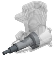
Pro/ENGINEER Wildfire 2.0 allows you to easily create 3D solid models, enabling you to visualize parts and assemblies with a realistic appearance. Based on material properties such as density, these models have mass, volume, surface area and other physical properties such as a center of gravity.
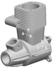
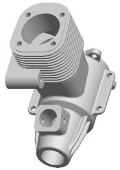
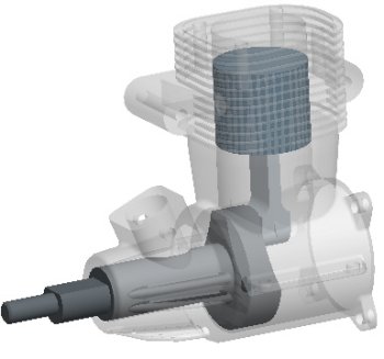
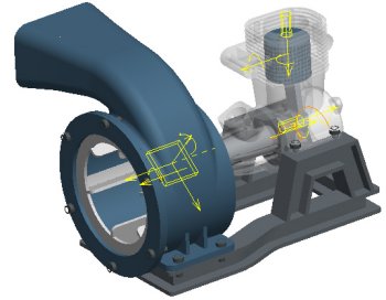
For example, consider the cast aluminum engine block shown below. This model was created in millimeters, and has the mass properties shown. The coordinate system labeled 123 indicates the center of gravity of the model.
The following are advantages of solid modeling:
- If the model changes (such as increasing the number of cooling fins), all of the mass properties would automatically update.
- Solid models also allow you to check tolerances and clearance/interference between components in an assembly.
|
Solid Model and its Mass Properties |
Feature Based
Pro/ENGINEER Wildfire 2.0 models are constructed using a series of features. Each feature builds upon the previous feature, creating the model one feature at a time. Individually each feature can be simple, but collectively can form complex parts and assemblies.
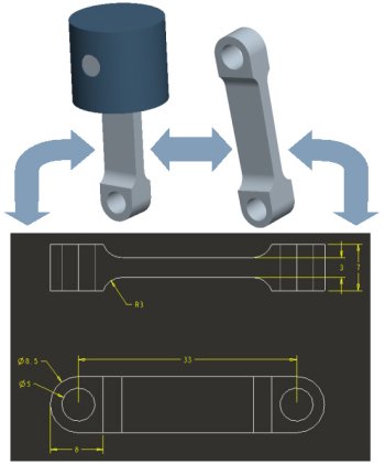
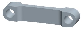
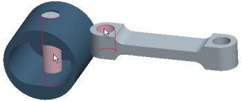
In the following figure, we have a connecting rod in the various stages of its creation:
- An Extrude feature forms the overall shape and size of the model.
- Additional Extrude features created at the top and bottom of the model.
- Hole features created at the top and bottom of the model.
- Round features created at the top and bottom of the model.
 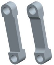 CONNECTING_ROD Features |
Parametric
Pro/ENGINEER Wildfire 2.0 models are driven using dimension values. If a dimension of a feature is changed, that solid feature will update. This change will then automatically propagate through the remaining features in the model, updating the entire part.
Parent/Child Relationships
Parent/Child relationships provide a powerful way to capture your "design intent" into a model. Parent/Child relationships are naturally created between features during the modeling process. When creating a feature, existing features that are referenced become parents to the new feature. Also, if the parent features are updated, the child features will automatically update accordingly.
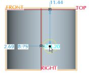
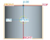
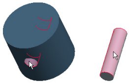
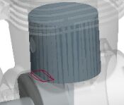
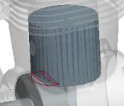
In the following figure, the PISTON model has a height of 18.5, with a hole dimensioned 8 from the top surface. The height dimension is then modified to 24, and the model is Regenerated to update its features. Notice that the parent/child relationship between the hole and the body of the model forces the hole to move upwards to maintain the 8 dimension.
|
|
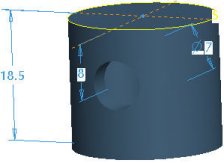
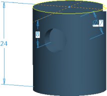
This behavior (the hole referencing the top surface) is an example of the design intent that was built into this model. Alternatively, the hole could have referenced the bottom surface, yielding a different effect when the model height is modified.
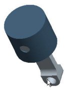
Associative & Model Centric
If a part model is changed in Pro/ENGINEER Wildfire 2.0, any assemblies or drawings that reference that model will automatically update. This behavior is known as Associativity and also works in reverse- if a model dimension in a drawing is updated, the part model and the assembly it is used in will update.
The part model is the central source of design information. Once a part model is created, it can be:
- Placed in an assembly- Depending on how components are assembled, the components can be stationary or allowed to move as a mechanism.
- Used to create a drawing- 2D views of the model can be quickly placed on a drawing sheet, and dimensions can be automatically shown.
|
Model Associativity |
Pro/ENGINEEER Wildfire 2.0 Interface
The following are basic components of the interface:
- Graphics Window- Large gray area where the model is visible.
- Navigator- collapsible panels on the left of the screen.
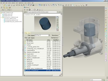
- Browser- A multi-functional web browser, shown displaying a list of models and a small preview window in the center of the screen.
- Model Tree- Lists the features of a part, or the components in an assembly on the left of the screen.
- Folder Browser (not shown)- Displays on the left of the screen in place of the model tree, and lists folders on your computer or network. You can browse folders and view their contents in the Browser.
- Main Menu- Located on the top of the screen, this pull-down menu has common menu options such as File, Edit, Insert, Tools, and Help.
- Main Toolbar- An icon toolbar located at the top of the screen.
- Feature Toolbar- An icon toolbar located at the right of the screen.
- Dashboard (not shown)- A dialog bar located at the bottom of the screen when creating features.
| Exercise 1: Opening, Orienting, and Editing Models |
Overview- In this exercise, you will learn three basic skills that are essential when modeling with Pro/ENGINEER Wildfire 2.0
- Preview and open design models- You will use the Navigator and Browser to browse folders, preview models, and open models.
- Orient design models- After opening an existing model, you will use a combination of keyboard and mouse commands to Spin, Pan, and Zoom models.
- Edit existing design models- After learning basic model orientation, you will use editing options to modify existing models.
|
|
Working Directory The Working Directory sets the default folder for opening and saving models. |
| Task 1-1. Open the ENGINE_BLOCK.PRT using the Navigator. |
- Start Pro/ENGINEER Wildfire 2.0 if necessary. The default web page displayed in the browser is the Pro/ENGINEER Wildfire 2.0 landing page.
- In the Folder Browser
 (left of the screen), locate the HOW_INTRO-WF2 folder, and expand it by clicking the '+'.
- Click on the ProE_models folder to view its contents in the browser.
- Right click on the ProE_models folder and select Set Working Directory.
- Select the ENGINE_BLOCK.PRT from the browser.
- Notice a model preview appears in the browser.
- Click Open File in Pro/E
 from the browser (to the right of the preview).
 ENGINE_BLOCK.PRT |
|
|
Model Orientation Commands Spin: Rotate the model on the screen. |
| Task 1-2. Practice using Spin, Pan, and Zoom with the ENGINE_BLOCK. |
- To spin the model, press and hold the middle mouse button and move the mouse in various directions.
- Click Saved View List
 from the main toolbar (top of the screen) and select Standard Orientation.
- Zoom in and out on the model:
- Place the mouse cursor over a desired area of the model
- Press CTRL, press and hold the middle mouse button, and move the mouse towards you to zoom in.
- Press CTRL, press and hold the middle mouse button, and move the mouse away from you to zoom out.
|
|
The location of the cursor determines the target area for zooming. |
- If you have a wheel mouse, try zooming by rolling the wheel:
- Roll the mouse wheel towards you to zoom in (without the CTRL key).
- Roll the mouse wheel away from you to zoom out.
- Click Saved View List from the main toolbar and select Standard Orientation.
- Pan the model around the screen:
- Press SHIFT, press and hold the middle mouse button, and move the mouse in various directions.
- Click Saved View List from the main toolbar and select Standard Orientation.
|
|
You can press CTRL + D as a shortcut to the Standard Orientation. |
|
|
Selecting with the Mouse Move the mouse over a feature to highlight it. Click the left mouse button to make a selection. Cyan (light blue) highlighting indicates an item is pre-selected. Red highlighting indicates an item is selected. Once a feature is selected, edges or surfaces of the feature will highlight, and could be selected. |
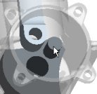
| Task 1-3. Select the mounting flange. |
- Highlight and select a feature as shown in the following figure:
- Place the cursor over the EXTRUDE_2 feature so it highlights in cyan.
- Select the EXTRUDE_2 feature by clicking on it, so it highlights in red.
|
|
Zoom in to make selection easier. |
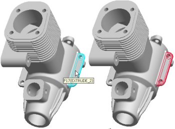 Highlighting a Feature |
- Click on the background to de-select the feature.
- Highlight and select EXTRUDE_2 again.
- Leave the feature selected and continue.
|
|
Edit Definition and Drag Handles The Edit Definition option opens the dashboard for a feature, where any desired changes to a feature can be made. A 'right-click and hold' technique is used to access popup menus, whereas a quick 'right-click and release' will pre-highlight the next feature beneath the cursor. Drag handles are small white squares located on the yellow feature preview. |
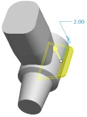
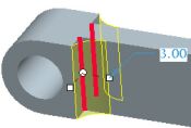
| Task 1-4. Edit the definition of the mounting flange (EXTRUDE_2) to make it thicker. |
- With EXTRUDE_2 still selected, right-click and hold, and then select Edit Definition.
- Notice that features created after this extrude are not shown during redefinition.
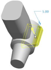
- Drag the depth handle on the model (white square on the yellow preview) from 2 to 5, as shown in the following figure.
- Notice the depth value has updated in the dashboard (bottom of the screen).
|
Redefining a feature |
- Click Complete Feature
 from the right of the dashboard (bottom of the screen).
- The model will take a few moments to regenerate the many features that come after the extrude we redefined.
- Notice that this change has also affected the opposite side, due to the existing Parent/Child relationships.
|
|
Editing Feature Dimensions You can Edit a feature to display its dimensions, and then enter new values. You then must Regenerate the model to update the changes. |
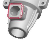
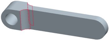
| Task 1-5. Edit the dimensions of the carburetor mount, and then undo the changes. |
- Highlight and select the extrude feature as shown in the following figure.
 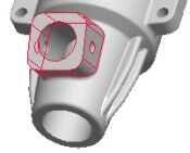 Selecting a Feature |
- Right-click and hold, then select Edit. The section and dimensions of the feature appear.
- Double-click on the 14.5 dimension, type 11.5, and press ENTER.
- Click Regenerate
 from the main toolbar (top of the screen) to update the model.
  Model Regenerated |
- Click Undo
 from the main toolbar (top of the screen) to reverse the last edit.
|
|
You can press CTRL + Z as a shortcut to Undo. |
|
|
Creating a Round Rounds allow you to add or remove material from a model by applying a radius to an edge. You can simply select an edge, set the radius, and complete the feature. |
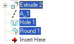
| Task 1-6. Create a round on the carburetor mount to smooth off a sharp edge. |
- Start the Round Tool
 from the feature toolbar (right of the screen).
- Select the edge shown in the following figure.
- Notice the round automatically follows the tangent chain of edges.
  Selecting an Edge |
- Drag either radius handle (white square on the yellow preview) to a value of 1.
- Click Complete Feature from the dashboard (bottom of the screen).
- Notice the Round feature is placed at the bottom of the model tree (left of the screen)
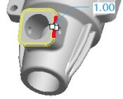  Round Created |
|
|
Undo / Redo You can use the Undo and Redo options to correct unintentional actions. |
| Task 1-7. Delete the round and Undo the deletion. |
- With the round still selected (highlighted in red), right-click and hold, select Delete, then click OK.
- Click Undo from the main toolbar to return the feature to the model.
- Click Save
 from the main toolbar and click OK.
- Click File > Close Window
 .
.
|
|
Models remain in session memory until Erased. |
This completes the first exercise.
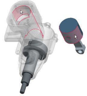
| Exercise 2: Creating Part Models |
Overview - In this exercise you will learn basic part modeling skills by creating three part models:
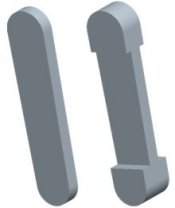
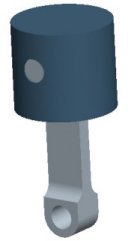
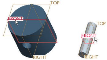
- PISTON_PIN.PRT
- PISTON.PRT
- CONNECTING_ROD.PRT
  PISTON_PIN and PISTON |
 CONNECTING_ROD |
|
|
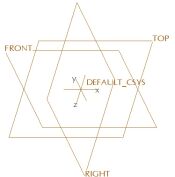
Creating Part Models New Part models are created from a default template, which contains default datum planes and a coordinate system. Default datum planes provide 3 orthogonal planes in 3D space that can be used as initial references when creating features on models. |
| Task 2-1. Create the PISTON_PIN model using the default template. |
- Click New
 from the main toolbar and select Part as the Type. Type PISTON_PIN as the Name and press ENTER.
 New Part Model |
- Click Datum Axes
 , Datum Points
  , and Coordinate Systems
  from the main toolbar (top of the screen) to disable their display.
|
|
Creating Sketches A Sketch is a basic 2D shape used to create a feature, and is created on a planar reference. Once created, sketches may be easily used to create 3D features. |
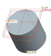
| Task 2-2. Create a circular sketch to be used for the main body of the model. |
- Start the Sketch Tool
 from the feature toolbar (right of the screen).
- Select datum plane FRONT from the model, and click Sketch from the Sketch dialog box.
- Click Close from the References dialog box.
- Click Datum Planes
 from the main toolbar (top of the screen) to disable their display.
- Sketch a circle as shown in the following figure:
- Click Circle
 from the sketcher toolbar (right of the screen).
- Position the cursor to snap at the intersection of the datum planes.
- Click and release to place the circle center, move the mouse outward, then click and release again.
- Notice that a dimension is automatically created.
- Click Select Items
 from the sketcher toolbar (right of the screen) to allow items to be selected.
- Double-click the diameter dimension value, type 5, and press ENTER.
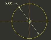 Creating a sketch |
- Click Complete Sketch
 from the sketcher toolbar (right of the screen).
- Click Saved View List from the main toolbar and select Standard Orientation.
- Click Datum Planes from the main toolbar to enable their display.
|
|
Using the Extrude Tool The Extrude tool allows you to take a sketch and linearly extrude it to create a feature. You can add material (protrusion) or remove material (cut) when using the Extrude tool. |
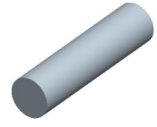
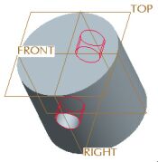
| Task 2-3. Create an Extruded protrusion using the previous sketch. |
- With the sketch still selected (highlighted in red), create an Extrude feature as shown in the following figure:
- Start the Extrude Tool
 from the feature toolbar (right of the screen).
- Drag the depth handle (white square on the yellow preview) to 4.
- Click the black arrow on the Depth Options Flyout
 in the dashboard (bottom of the screen) and select Both Sides
  .
.
- Type 20 in the dashboard and for the depth and press ENTER.
- Click Refit
 from the main toolbar (top of the screen).
- Click Complete Feature from the dashboard (bottom of the screen).
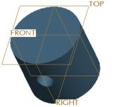
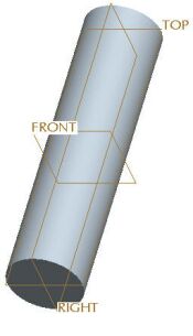 Extrude Feature Created |
- Click Save from the main toolbar and click OK.
- Click File > Close Window .
|
|
Creating the PISTON The PISTON also starts off using a circular sketch, but it is placed on a different plane. |
| Task 2-4. Create the PISTON.PRT, and create the first Sketch. |
- Click New from the main toolbar and select Part as the Type.
- Type PISTON as the Name and press ENTER. A new part model is created from the default template.
- Start the Sketch Tool from the feature toolbar (right of the screen).
- Select datum plane TOP from the model, and click Sketch from the Sketch dialog box.
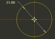
- Sketch a circle as shown in the following figure:
- Click Close from the References dialog box.
- Click Datum Planes from the main toolbar (top of the screen) to disable their display.
- Click Circle from the sketcher toolbar (right of the screen).
- Click and release to place the circle center, move the mouse outward, then click and release again.
- Click Select Items from the sketcher toolbar to allow items to be selected.
- Double-click the diameter dimension, type 21, and press ENTER.
Creating a Sketch
- Click Complete Sketch from the sketcher toolbar.
- Click Saved View List from the main toolbar and select Standard Orientation.
- Click Datum Planes from the main toolbar to enable their display.
|
|
Changing the Depth Direction You can flip the feature to the other side of its sketching plane by using the Change Depth Direction option. |
|
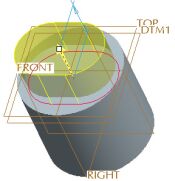
Task 2-5. Use the previous sketch to create the first Extrude feature. |
- With the sketch still selected, create an Extrude feature as shown in the following figure:
- Start the Extrude Tool from the feature toolbar (right of the screen).
- Double-click on the depth value, type 18.5, and press ENTER.
- Click Change Depth Direction
 in the dashboard (bottom of the screen) to flip the direction of feature creation downward.
- Click Complete Feature from the dashboard.
|
|
The snapping interval for drag handles is currently set to 1mm. |
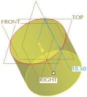 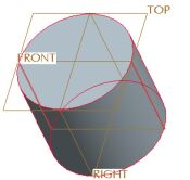 Extrude Feature Created |
|
|
Creating a Group of Features The next solid feature to be created is an Extruded Cut to hollow out the PISTON. In order to capture the desired dimensioning scheme for the cut, its sketch will be placed on a datum plane offset from the top surface of the model. We will start the Extrude tool and Pause it. We will then create the datum plane and the sketch. When the Extrude tool is Resumed and completed, the system automatically creates a Group in the model tree. A group allows us to edit and manipulate several features as one. |
| Task 2-6. Start the Extrude tool and then create a datum plane. |
- Start the Extrude Tool from the feature toolbar (right of the screen).
- Click Pause Feature
 from the right of the dashboard. (bottom of the screen)
 - Notice the dashboard grays-out, indicating it is paused.
- Start the Datum Plane Tool
 from the feature toolbar (right of the screen). .
- Select datum plane TOP from the model, and drag the offset handle downward to 2.
- Click OK from the Datum Plane dialog box.
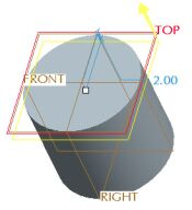  Datum Plane Created |
|
|
Using Centerlines in a Sketch Centerlines promote symmetry when sketching. In this example, we want a rectangle to be sketched symmetrically about the vertical and horizontal references. Centerlines display as a yellow dashed line. |
| Task 2-7. Sketch on the previous datum plane. Begin by sketching a symmetric rectangle. |
- With the datum plane still selected, start the Sketch Tool from the feature toolbar.
- Notice that datum plane DTM1 is automatically selected as the Sketching Plane.
- Click Sketch from the Sketch dialog box.
- Click Close from the References dialog box.
- Click Datum Planes from the main toolbar (top of the screen) to disable their display.
- Click No Hidden
 from the main toolbar.
- Notice that there are two tan dashed lines, these are sketcher references. Sketched geometry will snap to these references.
-
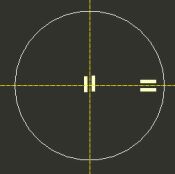
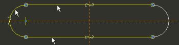
Sketch centerlines and a rectangle as shown in the following figure:
- Click the black arrow on the Line Types Flyout
 in the sketcher toolbar (right of the screen), and select Centerline
  .
.
- Click two locations on the vertical sketcher reference to sketch a vertical centerline
- Sketch another centerline on the horizontal sketcher reference, as shown on the left.
- Click Rectangle
 from the sketcher toolbar (right of the screen).
- Click and release to select a location for the upper left corner of the rectangle.
- Allowing the rectangle to snap to symmetry, click and release to select a location for the lower right corner of the rectangle.
|
Sketching Centerlines and a Rectangle |
|
|
Always use a 'click-and-release', 'click-and-release' technique when sketching geometry, as opposed to holding down the left mouse button and 'dragging'. |
|
|
Sketching Arcs The Arc tool can create both 3-point and tangent-end arcs. In this task, we will be creating a Tangent Arc. |
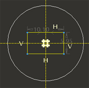
| Task 2-8. Continue the sketch to create an oval shape. Begin by sketching tangent arcs using the rectangle as a guide. |
-
Click Arc
 from the sketcher toolbar (right of the screen).
 - Click and release on the upper right vertex of the rectangle to start the arc.
- Move the cursor rightward out of the green quadrant symbol to continue the arc.
- Click and release on the lower right vertex of the rectangle to complete the arc.
- With Arc still depressed, sketch a similar arc on the left of the rectangle (this time, move the cursor leftward out of the green quadrant symbol).
  Sketching Tangent Arcs |
|
|
Always use a 'click-and-release', 'click-and-release' technique when sketching geometry, as opposed to holding down the left mouse button and 'dragging'. |
- Middle-click to stop sketching and to allow items to be selected.
- Notice that Select Items is now depressed in the sketcher toolbar.
- Press CTRL and select the two vertical lines.
- Right-click and hold, then and select Delete.
- Notice that Select Items
|
|
Creating Dimensions Many different dimension types are created with the Dimension tool. To create a dimension, select item(s) to be dimensioned and then middle-click to locate the dimension value |
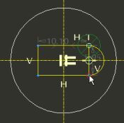
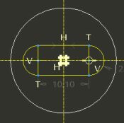
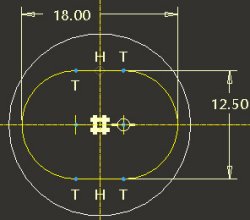
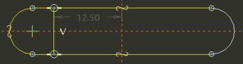
| Task 2-9. Complete the oval-shaped sketch by creating dimensions. |
- Click Dimension
 from the sketcher toolbar (right of the screen).
- Select each arc, position the cursor above the sketch, and middle-click to place the dimension.
- Select Horiz from the Dim Orientation dialog box that appears and click Accept.
- With Dimension still depressed, select the top and bottom lines.
- Position the cursor to the right of the sketch, and middle-click to place the dimension.
- Middle-click to stop sketching and to allow items to be selected. Notice that Select Items is now depressed.
- Double-click on the horizontal dimension, type 18, and press ENTER.
- Double-click on the horizontal dimension, type 12.5, and press ENTER.
|
Creating Dimensions |
- Click Complete Sketch from the sketcher toolbar.
- Click Saved View List from the main toolbar and select Standard Orientation.
- Click Datum Planes from the main toolbar to enable their display.
- Click Shading
 from the main toolbar.
|
|
Completing the Group of features Now that the datum plane and sketch have been created, we will Resume and complete the Extrude feature, creating an oval cut that hollows out the PISTON. |
| Task 2-10. Complete the Extruded cut using the previous sketch. |
- With the sketch still selected, complete the Extrude feature as shown in the following figure:
- Click Resume Feature
 from the dashboard.
- Click the yellow depth direction arrow on the model to flip the direction downward.
- Click the black arrow on the Depth Options Flyout in the dashboard and select Through All
 .
.
- Click Remove Material
 from the dashboard, and then click Complete Feature .
- Press and hold the middle mouse button to spin the model, and view the cut on the underside.
|
|
Many feature operations can be done by right clicking on drag handles or the model, or by using the icons in the dashboard. |
|
|
|
|
Auto Groups The datum plane and sketch have been automatically grouped with the Extrude feature. These features are also automatically Hidden, so they will not clutter up the display. Hidden features are 'grayed-out' in the model tree. |
| Task 2-11. Examine the created group in the model tree. |
- Locate the EXTRUDE_2 group in the Model Tree.
- Notice that the Extruded Cut feature was automatically grouped with the datum plane and sketch used to define it.
 Model Tree |
|
|
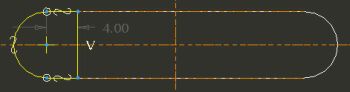
Creating Linear Holes Holes remove material from a model and have a cylindrical shape by default. Linear holes require Primary and Secondary references. The primary reference is placement plane, and the secondary references dimensionally locate the hole. |
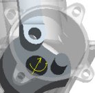
| Task 2-12. Begin creating a hole in the center of the PISTON. |
- Click Saved View List from the main toolbar and select Standard Orientation.
- Start the Hole Tool
 from the feature toolbar, and select datum plane FRONT from the model.
- Right-click and hold, then select Secondary References.
- Press CTRL and select datum planes TOP and RIGHT from the model to dimensionally locate the hole.
|
|
Notice that you must press and hold the CTRL key to select multiple references. |
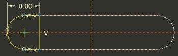
- Continue the hole as shown in the following figure:
- Click Saved View List from the main toolbar and select FRONT.
- Drag the location handle (in the center of the hole) to position the hole approximately as shown on the left.
- Select the Placement tab in the dashboard, modify the offset value
from datum plane TOP to 8, and press ENTER. - Change the dimension type for datum plane RIGHT from Offset to Align.
  Positioning the Hole |
| Task 2-13. Complete the hole in the center of the PISTON. |
- Complete the hole as shown in the following figure:
- Click Saved View List from the main toolbar and select Standard Orientation.
- Click the Shape tab in the dashboard.
- Change the existing depth option from Blind to Through All.
- Change the depth option for Side 2 from None to Through All.
- Type 5 for the diameter in the dashboard, and press ENTER.
- Click Complete Feature .
  Hole Created |
|
|
You can also middle-click as a shortcut to Complete Feature |
|
|
Applying Color to Models You can use the Color and Appearance dialog box to create and apply colors for models. In this case, a basic color palette has been pre-loaded. |
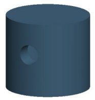
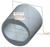
| Task 2-14. Apply a color appearance to the model. |
- Click Datum Planes from the main toolbar to disable their display.
- Click View > Color and Appearance from the main menu.
- Select the Blue_Dark appearance (3rd sphere in the top row) and click Apply.
- Click Close from the Appearance Editor dialog box.
Completed PISTON |
- Click Save from the main toolbar and click OK.
- Click File > Close Window .
|
|
Creating the CONNECTING ROD We will create the body of the CONNECTING_ROD using an oval-shaped sketch and extrude. |
| Task 2-15. Create the CONNECTING_ROD and begin a sketch. |
- Click Datum Planes from the main toolbar to enable their display.
- Click New from the main toolbar and select Part as the Type.
- Type CONNECTING_ROD as the Name and press ENTER
- Start the Sketch Tool from the feature toolbar.
- Select datum plane FRONT from the model, and click Sketch from the Sketch dialog box.
- Click Close from the References dialog box.
- Click Datum Planes from the main toolbar to disable their display.
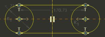
- Begin the sketch of an oval by sketching two circles as shown in the following figure:
- Click Centerline from the sketcher toolbar. Sketch a centerline by clicking two locations on the vertical reference.
- Click Circle from the sketcher toolbar. Click a location on the horizontal reference for the center of the left circle, then complete the circle.
- Click a location on the horizontal reference for the center of the right circle, then move the mouse outwards until the radius snaps to the radius of the first circle, then click again to complete it.
- Click Constraints
 from the sketcher toolbar.
- Click Symmetric
 , and select the center of each circle and then the centerline.
- Click Close from the Constraints dialog box.
 Sketching Circles |
|
|
Tangent Lines and Dynamic Trim The 2-Tangent Line allows you to easily sketch lines tangent to 2 entities. The Dynamic Trim tool allows you to remove unwanted portions of sketched entities. A freehand curve is dragged through the sketch, and any entities intersected by it will be deleted. |
| Task 2-16. Continue the oval sketch for the CONNECTING_ROD. |
- Continue the sketch as shown in the following figure:
- Click the black arrow on the Line Types Flyout
 in the sketcher toolbar and select 2-Tangent Line
  .
.
- Allowing the cursor to snap to the circles, sketch two horizontal lines as shown.
 Sketching Lines |
-
Click Dynamic Trim
 from the sketcher toolbar.
- Place the cursor inside one of the circles.
- Click and hold the left mouse button, and then drag a freehand curve through the inner arcs to remove them (any entities intersected by the freehand curve will be deleted).
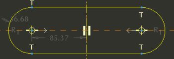 Trimming Completed |
|
|
Click Undo |
| Task 2-17. Complete the sketch and create a symmetric Extrude. |
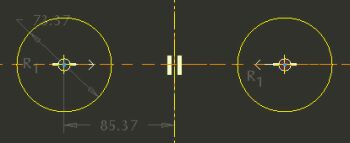
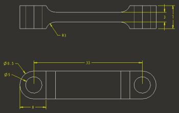
- Dimension the sketch as shown in the following figure:
- Click Dimension from the sketcher toolbar.
- Select the center of each arc and middle-click above the sketch to place the horizontal dimension.
- Double-click the left arc and then middle-click to the left of the sketch to place the diameter dimension.
- Middle-click to stop sketching and to allow items to be selected.
- Double-click on the diameter dimension, type 8.5, and press ENTER.
- Double-click on the length dimension, type 33, and press ENTER.
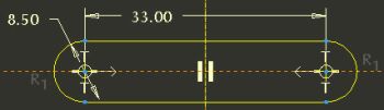 Creating and Modifying Dimensions |
- Click Complete Sketch from the sketcher toolbar.
- Click Saved View List from the main toolbar and select Standard Orientation.
- Click Datum Planes from the main toolbar to enable their display.
- With the sketch still selected, create an Extrude feature as shown in the following figure:
- Start the Extrude Tool from the feature toolbar.
- Click the black arrow on the Depth Options Flyout in the dashboard and select Both Sides .
- Drag the depth handle to 3.
- Click Complete Feature from the dashboard.
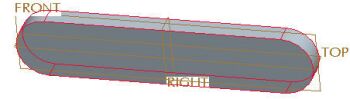 Extrude Completed |
|
|
Tracing Existing Geometry You can use the Entity from Edge tool to trace existing geometry. The created entities will 'snap' to the existing geometry without the need for dimensions. |
| Task 2-18. Begin creating a second sketch by tracing existing geometry. |
- Start the Sketch Tool from the feature toolbar.
- Click Use Previous and then click Sketch from the Sketch dialog box.
- Sketch as shown in the following figure:
- Click Close from the References dialog box.
- Click Datum Planes from the main toolbar to disable their display.
- Click No Hidden from the main toolbar.
- Click Entity from Edge
 from the sketcher toolbar.
- Select the arc and the two straight edges as shown in the following figure.
- Click Close from the Type dialog box.
 Creating Entities from Edges |
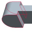
| Task 2-19. Continue the sketch by sketching lines and trimming. |
-
Click Line
 from the line types flyout in the sketcher toolbar.
- Sketch a vertical line snapping to the existing lines, and middle-click to stop sketching.
- Click Dynamic Trim from the sketcher toolbar.
- Click and drag to sketch a freehand curve to remove the unwanted horizontal line segments as shown in the bottom figure.
- Ignore any dimension values for now.
|
Sketching a Line and Dynamic Trim |
| Task 2-20. Dimension and complete the sketch. |
- Click Dimension from the sketcher toolbar.
- Select the arc, and the vertical line, then middle-click to place the dimension.
- Middle-click to stop sketching and to allow items to be selected.
- Double-click on the dimension value, type 8, and press ENTER.
 Dimension Created |
- Click Complete Sketch from the sketcher toolbar.
- Click Saved View List from the main toolbar and select Standard Orientation.
- Click Shading from the main toolbar.
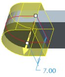
| Task 2-21. Create an extrude forming the enlarged end of the model. |
- With the sketch still selected, start the Extrude Tool from the feature toolbar.
- Click the black arrow on the Depth Options Flyout in the dashboard and select Both Sides .
- Drag the depth handle to 7.
- Click Complete Feature from the dashboard.
|
|
You can also right-click on depth handles and select the desired depth option. |
|
Protrusion Created |
|
|
Datum Axes Datum Axes are linear references that can be used to create other features. |
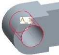
| Task 2-22. Create a datum axis in the end of the model. |
- Click Datum Axes from the main toolbar (top of the screen) to enable their display.
- Start the Datum Axis Tool
 from the feature toolbar (right of the screen).
- Select the cylindrical surface shown in the following figure and click OK from the Datum Axis dialog box.
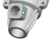
 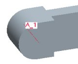 Creating a Datum Axis |
|
|
Coaxial Holes Coaxial Holes use a datum axis for location, but also require a placement plane as a secondary reference. |
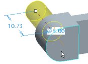
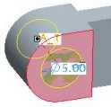
| Task 2-23. Create a coaxial hole on the previous axis. |
- With the axis still selected, start the Hole Tool from the feature toolbar.
- Right-click and hold, then select Secondary References.
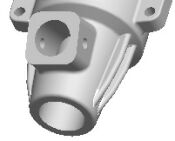
- Select the "D-shaped" surface shown on the upper left as the placement plane.
- Right-click on the depth handle and hold, then select Through All.
- Notice the diameter dimension is set to 5 from the previous hole.
- Click Complete Feature from the dashboard.
|
Creating a Hole |
- Click Datum Axes from the main toolbar to disable their display.
|
|
Selecting Multiple Round References Press CTRL to select multiple edges for a single round set. |
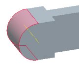
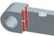
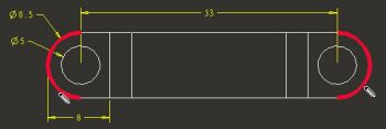
| Task 2-24. Create a round to add strength to the end of the model. |
- Start the Round Tool from the feature toolbar.
- Press CTRL and select the two inner edges shown in the following figure.
- Drag either radius handle to 3.
- Click Complete Feature from the dashboard.
|
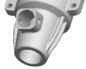
Creating a Round |
|
|
Mirroring Features You can use the Mirror tool to mirror feature(s) about a selected plane. |
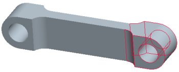
| Task 2-25. Mirror a series of features to quickly create the opposite side of the CONNECTING_ROD. |
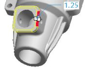
- Press CTRL and select the following four features from bottom of the Model Tree (left of the screen).
 Selecting Features |
- Start the Mirror Tool
 from the feature toolbar (right of the screen).
- Select datum plane RIGHT from the Model Tree (left of the screen).
- Click Complete Feature from the dashboard.
 Features Mirrored |
|
|
Pro/ENGINEER Wildfire has a number of editing tools to quickly duplicate features, including Mirror, Copy/Paste, and Pattern. |
- Click Save from the main toolbar and click OK.
- Click File > Close Window .
This completes the second exercise.
| Exercise 3: Creating Assemblies |
Overview- In this exercise you will learn basic assembly modeling skills by creating an assembly and running a simple mechanism:
- PISTON_ASSY.ASM
- ENGINE.ASM
 PISTON_ASSY Assembly |
 ENGINE Assembly |
|
|
Creating Assembly Models New Assembly models are created from a default template, which contains default datum planes and a coordinate system. The first component in an assembly is typically placed with a Default constraint, which centers the component in the assembly. |
| Task 3-1. Create the PISTON_ASSY assembly and add the PISTON part. |
- Click Datum Planes from the main toolbar to enable their display.
- Click New and select Assembly as the Type.
- Type PISTON_ASSY as the Name and press ENTER. A new assembly model is created from the default template.
- Click Add Component
 from the feature toolbar (on the right).
- Select PISTON.PRT and click Open.
- Click Default Location
 from the Component Placement dialog box, and click OK.
- Press CTRL and select datum planes ASM_RIGHT, ASM_TOP, and ASM_FRONT from the Model Tree.
- Right-click and hold, then select Hide.
 PISTON.PRT Assembled |
|
|
Assembling with Constraints You can assemble components together by creating various types of Constraints. Constraints can be used to assemble components in a fixed position. Constraints can be created by selecting corresponding pairs of geometry from the component being assembled and an existing component. |
| Task 3-2. Assemble the PISTON_PIN with Align and Insert constraints. |
- Click Add component from the feature toolbar.
- Select PISTON_PIN.PRT and click Open.
- Select datum plane FRONT from the PISTON and the PISTON_PIN, as shown in the following figure.
- Notice this has created an Align constraint in the dialog box.
 Selecting Datum Planes |
-
If necessary, drag the Component Placement dialog box downward to access the main toolbar.
-
Click Datum Planes from the main toolbar to disable their display.
-
Select the cylindrical surfaces from the PISTON.PRT and PISTON_PIN.PRT, as shown in the following figure.
- Notice this has created an Insert Constraint in the dialog box.
- Click OK from the Component Placement dialog box.
 Selecting Surfaces |
|
|
Assembling with Connections You can assemble components together in an assembly by creating various types of Connections. Connections can be used to create realistic mechanical joints between components. These joints will allow assembly components to move as a mechanism. |
| Task 3-3. Begin assembling the CONNECTING_ROD with a Pin connection. |
- Click Add component from the feature toolbar.
- Select CONNECTING_ROD.PRT and click Open.
- Select the Connect tab in the Component Placement dialog box.
- Notice the default connection is set to Pin.
- Press and hold the middle mouse button to spin the assembly, and then select the cylindrical surfaces as shown in the following figure.
 Selecting Surfaces |
- Click Saved View List from the main toolbar and select Standard Orientation.
|
|
Using the Search Tool The Search Tool provides an easy way to select items that are not visible. |
| Task 3-4. Complete the Pin connection on the CONNECTING_ROD. |
- Search for the first datum plane:
- Start the Search Tool
 from the main toolbar.
- Select Datum Plane as the Look For object.
- Select PISTON.PRT as the Look In object.
- Click Find Now, select the FRONT datum plane, and click Add Item
 .
.
- Click Close.
- Start the Search Tool
- Search for the second datum plane:
- Start the Search Tool from the main toolbar again, and click Find Now.
- Select the FRONT datum plane, click Add Item , then click Close.
- The Pin joint is now defined. Click OK from the Component Placement dialog box.
- Start the Search Tool
- Click Drag Component
 from the main toolbar.
- Click and release to move the connecting rod as shown.
- Click to accept the new position.
- Middle-click when finished.
 PISTON_ASSY.ASM |
- Click Save from the main toolbar and click OK.
- Click File > Close Window .
| Task 3-5. Open the ENGINE assembly. |
-
Select the Folder Browser (left of the screen), and select the ProE_models folder.
-
Select the ENGINE.ASM from the browser, and click Open File in Pro/E.
|
|
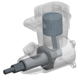
A transparent appearance has been applied to the ENGINE_BLOCK.PRT within the ENGINE.ASM. |
 ENGINE.ASM |
|
|
Running a Mechanism A Mechanism refers to components that have been assembled using Connections. Connections can be used to allow components to move as realistic mechanical joints. |
| Task 3-6. Run the existing mechanism. |
- Click Applications > Mechanism from the main menu.
- Click Run Analysis
 from the Mechanism Toolbar (right of the screen).
- Select RUN_ENGINE and click Run.
- Notice the CRANKSHAFT rotates 360 degrees.
- Click Close from the Analyses dialog box.
- Click Run Analysis
- Click Applications > Standard from the main toolbar,
- Click Yes from the message window.
- Click Saved View List from the main toolbar and select Standard Orientation.
|
|
Assembling with Connections A Cylinder connection allows a component to rotate and translate along the rotation axis. |
| Task 3-7. Add the PISTON_ASSY to the ENGINE assembly, then create a Cylinder connection. |
- Click Add component from the feature toolbar.
- Select PISTON_ASSY.ASM and click Open.
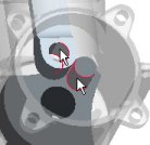
- Create a cylinder connection as shown in the following figure:
- Press CTRL + ALT, then press and hold the right mouse button to drag the PISTON_ASSY.ASM as shown.
- Select the Connect tab from the Component Placement dialog box.
- Change the Connection Type from Pin to Cylinder.
- Select the cylindrical surfaces as shown.
 Selecting Surfaces |
| Task 3-8. Create a second cylinder connection on the PISTON_ASSY. |
- Create a cylinder connection as shown in the following figure:
- Press and hold the middle mouse button to spin the entire assembly as shown in the upper left.
- Press CTRL, press and hold the middle mouse button, and move the mouse towards you to zoom in.
- Press CTRL + ALT, then press and hold the left mouse button to drag the CRANKSHAFT as shown in the upper right.
- Click New Constraint
 from the Component Placement dialog box.
- Zoom in and select the cylindrical surfaces as shown on the bottom.
|
Selecting Surfaces |
- Press CTRL + ALT, then press and hold the left mouse button to drag the CRANKSHAFT again.
- The CRANKSHAFT pin should now align with the hole in the CONNECTING_ROD, and the PISTON_ASSY should now rotate with the CRANKSHAFT.
- Click OK from the Component Placement dialog box.
- Click Saved View List from the main toolbar and select Standard Orientation.
 Completed Connections |
|
|
Running a Mechanism You can enter Mechanism Mode to run a mechanism. With the PISTON_ASSY assembled using connections, it will now move when the CRANKSHAFT rotates. |
| Task 3-9. Run the ENGINE mechanism again. |
-
Click Applications > Mechanism from the main menu.
- Click Run Analysis from the Mechanism Toolbar (right of the screen).
- Select RUN_ENGINE and click Run. Notice the mechanism rotates 360 degrees.
- Click Close from the Analyses dialog box.
- Click Run Analysis
- Click Save from the main toolbar and click OK.
- Click File > Close Window and click Yes from the message window.
- Click File > Erase > Not Displayed > OK to erase all models from session memory.
This completes the third exercise.
CONGRATULATIONS !
You have completed the part and assembly modeling portion of the Introduction Hands-On Workshop Tutorial.
If you wish, please continue with 2 Challenge exercises:
- Creating Drawings (10 pages)
- Model Associativity (5 pages)
SUMMARY
Now that you have completed this section of the tutorial, you should be able to:
- Describe Pro/ENGINEER Wildfire fundamentals.
- Navigate the Pro/ENGINEER Wildfire interface.
- Preview, open, and orient design models.
- Create basic part models.
- Create an assembly.
- Run a simple mechanism.
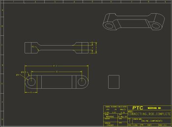
| Exercise 4: Creating Drawings (CHALLENGE) |
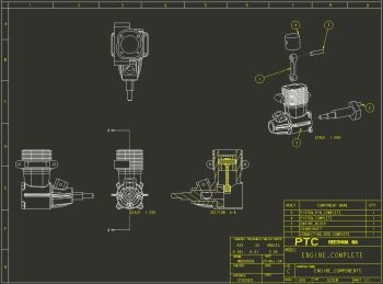
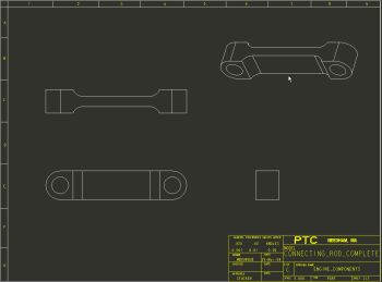
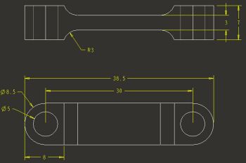
Overview- In this exercise you will learn basic drawing creation skills by creating a 2-sheet drawing called ENGINE_COMPONENTS, detailing the ENGINE assembly and the CONNECTING_ROD:
- ENGINE_COMPONENTS.DRW - sheet 1
- ENGINE_COMPONENTS.DRW - sheet 2
|
ENGINE_COMPONENTS.DRW - sheet 1 and 2 |
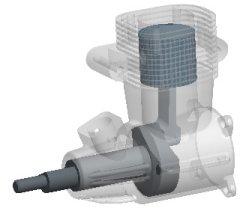
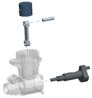
| Task 4-1. Open the ENGINE_COMPLETE assembly. |
- Select the Folder Browser , and select the ProE_models folder.
- Select the ENGINE_COMPLETE.ASM from the browser, and click Open File in Pro/E .
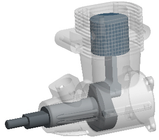 ENGINE_COMPLETE.ASM |
|
|
Cross Sections There are two differences between the ENGINE_COMPLETE.ASM and the one you created: There is a Cross Section and an Explode State pre-created for you. These will be used in the creation of the drawing. |
| Task 4-2. Examine the cross section in the ENGINE_COMPLETE assembly. |
- Start the View Manager
 from the main toolbar.
- Select the Xsec tab and double-click A to view the cross-section.
- Click Display > Flip from the View Manager dialog box.
- Double-click on No Cross Section.
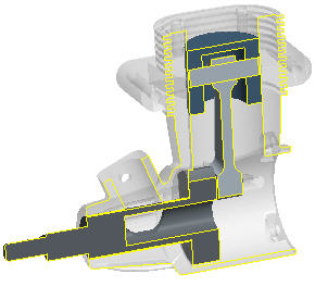 Cross Section A |
|
|
Explode States There are two differences between the ENGINE_COMPLETE.ASM and the one you created: There is a Cross Section and an Explode State pre-created for you. These will be used in the creation of the drawing. |
| Task 4-3. Examine the explode state in the ENGINE_COMPLETE assembly. |
-
From the View Manager dialog box, select the Explode tab.
- Double-click on Exp_1 to view the explode state.
- Right-click in the View Manager dialog box and select Unexplode.
- Click Close from the View Manager dialog box.
|
|
|
|
Creating Drawings A Drawing allows you to place 2D and 3D views of a part or assembly model on 2D drawing sheets for manufacturing purposes. You can rapidly create drawings by using a Drawing Template. A Drawing Template has pre-configured view locations, and can contain a format with a title block. |
| Task 4-4. Create a drawing of the ENGINE_COMPLETE assembly using a template. |
- Click File > Close Window .
- Click New and select Drawing as the Type.
- Type ENGINE_COMPONENTS as the Name and press ENTER.
- Notice that the ENGINE_COMPLETE.ASM is used as the Default Model, and that drawing_template is the current template.
- Click OK from the New Drawing dialog box.
- Enter parameter information to create the drawing as shown in the following figure:
- Type YOUR NAME at the prompt and press ENTER.
- The new drawing is created, which uses the template to place 4 isometric views, an exploded view, a title block, and a bill of materials.
- Double-click the date cell in the title block to the right of your name and enter &todays_date.
- Click OK from the Note Properties dialog box.
|
|
The '&todays_date' syntax uses a system parameter to display the date. |
 Drawing Created |
|
|
Creating Drawings In addition to using a Drawing Template, you can place views on a drawing sheet manually. First, a General view is placed. A General view can be placed in any orientation. |
| Task 4-5. Add a second sheet and create a view of the CONNECTING_ROD. |
- Select on the drawing background, then right-click and select Properties.
- Click Drawing Models > Add Model from the menu manager (right of the screen).
- Select the CONNECTING_ROD_COMPLETE.PRT and click Open.
- Click Insert > Sheet from the main menu to add a second sheet to the drawing.
- Type YOUR NAME at the prompt and press ENTER.
- Right click and select Insert General View.
- Select a location as shown in the following figure to place the view.
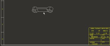 Placing the first General View. |
- Select FRONT as the Model View Name, and click OK from the Drawing View dialog box.
- Double-click the SCALE value in the lower left corner of the sheet, type 5, and press ENTER.
|
|
Creating Drawings Once a General view is placed, you can create other views such as Projection views. |
| Task 4-6. Place a projected views of the CONNECTING_ROD. |
- Create a projected view as shown in the following figure:
- Select the previous FRONT view.
- Right-click and select Insert Projected View.
- Select a location above the first view as shown in the following figure.
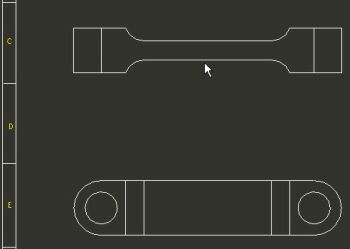 Placing the first Projection View |
- Create another projected view as shown in the following figure:
- Select the FRONT view again.
- Right-click and select Insert Projected View.
- Select a location to the right as shown in the following figure.
 Placing the second Projection View |
|
|
Creating Drawings General views can be placed in 2D or 3D orientations. |
| Task 4-7. Place a 3D general view of the CONNECTING_ROD. |
- Click on the background to de-select the current view.
- Right click and select Insert General View.
- Select a location as shown in the following figure to place the view.
- Click OK from the Drawing View dialog box.
- Right-click and uncheck Lock View Movement.
- Select and then drag views as necessary to position as shown.
 Placing the 3D General View. |
|
|
View Display Styles You can change the Display Style for views by editing their Properties. Display Styles include No Hidden, Hidden Lines, and Wireframe display. |
| Task 4-8. Set the display style for the TOP and RIGHT views to display hidden lines. |
- Click on the background to de-select the current view if necessary.
- Set the display style for two views:
- Press CTRL and select the TOP and RIGHT Projection views.
- Right-click and select Properties. Select Hidden as the Display Style and click OK.
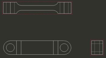 Hidden Lines Displayed |
|
|
Showing Dimensions You can quickly Show Dimensions that were created in the part model. Dimensions are created when modeling features, such as dimensioning a sketch, or entering the depth of a hole. |
| Task 4-9. Show and cleanup dimensions on the FRONT and TOP views. |
- Select the FRONT view, then right click and select Show Dimensions.
- Press CTRL, press and hold the middle mouse button, and move the mouse towards you to zoom in on the view.
- Select the 8 dimension, then drag to reposition it as shown in the following figure.
 Dimension Moved |
|
|
Cleaning Up Dimensions You can quickly Cleanup Dimensions in a view once they are shown. This spaces them out from the view. Only linear dimensions are effect by dimension cleanup. |
| Task 4-10. Show and cleanup dimensions on the FRONT and TOP views. |
- Click on the FRONT view, then right-click and select Cleanup Dimensions.
- Enter 0.5 for both the Offset and Increment values in the Clean Dimensions dialog box.
- Uncheck Create Snap Lines, and click Apply > Close.
-
Click Refit from the main toolbar.
- Select the TOP view, right click and select Show Dimensions.
- Right-click again and select Cleanup Dimensions.
- Click Apply > Close
|
|
Manipulating Dimensions Once dimensions are shown and cleaned up, you can further manipulate them. When a dimension is selected, several handles appear:
Several additional dimension editing options are available by selecting dimension(s), and using the right-click popup menu. |
| Task 4-11. Manipulate dimensions in the FRONT and TOP views. |
- Place the cursor between the FRONT and TOP views.
- Press CTRL, press and hold the middle mouse button, and move the mouse towards you to zoom in on the views.
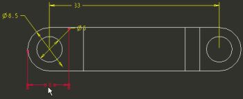
- Manipulate the dimensions as shown in the following figure:
- Select the diameter 8.5 dimension, right-click and select Flip Arrows.
- Select the diameter 5 dimension, right-click and select Flip Arrows. Then drag the dimension to position as shown. Drag the handle next to the dimension text to move the text to the left of the leader.
- Select the 8 dimension. Click and drag the handles at the end of the witness lines to position them as shown.
- Select the radius 3 dimension. Right-click and select Flip Arrows twice. Then drag the dimension to position as shown. Drag the handle next to the dimension text to move the text to the right of the leader.
- Select the 7 dimension. Click and drag the handles at the end of the witness lines to position them as shown.
 Dimensions Repositioned |
|
|
Creating Dimensions You can use the Create Dimension option to create a dimension on the drawing for geometry that doesn't already have a dimension. |
| Task 4-12. Create a dimension for the overall length of the CONNECTING_ROD. |
- Click Create Dimension
 from the drawing toolbar.
- Select the edges shown in the following figure.
 Selecting Edges |
- Middle-click above the 33 dimension to place the dimension.
- Click Tangent > Tangent > Horizontal > Return from the menu manager (right of the screen).
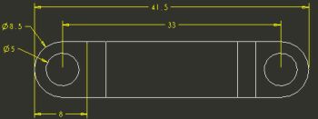 Driven Dimension Created |
- Select the FRONT view, right-click and select Cleanup Dimensions.
- Click Apply > Close. Notice the created dimension is spaced accordingly.
-
Click Refit from the main toolbar.
- Click Save and then click OK.
- Click File > Close Window .
This completes the fourth exercise.
| Exercise 5: Model Associativity (CHALLENGE) |
Overview- In this exercise you will experiment with associativity between part, assembly, and drawing modes. Associativity allows a change to be made in one mode to be reflected automatically in the other modes. You will perform the following tasks:
- Modify a part model and viewing the updated assembly.
- Examine interference in the assembly.
- Modifying a dimension from the drawing and view the updated part.
- Re-examine the assembly to verify the interference has been resolved.
| Task 5-1. Change a dimension on the body of the CONNECTING_ROD to make it longer. |
- Select the Folder Browser , and select the ProE_models folder.
- Select the ENGINE_COMPLETE.ASM from the browser, and click Open File in Pro/E .
- Select the ENGINE_COMPLETE.ASM from the browser, and click Open File in Pro/E
|
|
IMPORTANT- In the next step, you will be opening a second Pro/ENGINEER window. You must resize and reposition the window to the right of the tutorial. |
-
Click the '+' to expand PISTON_ASSY_COMPLETE in the Model Tree.
- Select CONNECTING_ROD_COMPLETE.
- Right-click and hold, then select Open.
- Double-click on the main body of the model to view the dimensions for EXTRUDE 1.
- Double-click the 33 dimension, type 30, and press ENTER.
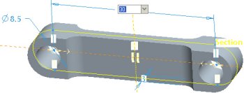 Editing a Dimension |
- Click Regenerate from the main toolbar to update the model.

You can also press CTRL + G to regenerate the model.
| Task 5-2. Regenerate the assembly to view the effects of shortening the CONNECTING_ROD. |
- Click Window > ENGINE_COMPLETE.ASM from the main menu.
- Click Regenerate from the main toolbar.
- The assembly shifts slightly due to the shorter CONNECTING_ROD.PRT.
 Updated Assembly |
|
|
Running a Mechanism Playback Once a Mechanism Analysis has been run, you can use the Replay Analysis option to 'animate' the mechanism in a continuous loop. You can also use the Global Interference option to check for any interference between components while viewing the playback. |
| Task 5-3. Run the mechanism playback to view the interference created by shortening the CONNECTING_ROD. |
- Click Applications > Mechanism from the main menu.
- Click Run Analysis from the Mechanism Toolbar (right of the screen).
- Select RUN_ENGINE and click Run from the Analyses dialog box. Then click Close.
- Click Replay Analysis
 from the Mechanism Toolbar (right of the screen).
- Select Global Interference and click Play
 from the Playbacks dialog box. (The interference will take a few seconds to calculate).
- Drag the Speed slider to maximum, and click Play
 from the Animate dialog box.
- Notice that interference is present (red highlighting) during the bottom of the stroke.
  Interference Detected |
- Click Stop
 when finished viewing the interference, and then click Close > Close.
- Click Drag Component
 from the mechanism toolbar (right of the screen).
- Double-click on Snaphot1 and click Close.
- Click Applications > Standard from the main menu, and click Yes from the message window.
- Click File > Close Window to return to the CONNECTING_ROD part.
| Task 5-4. View the effects on the drawing, and modify the CONNECTING_ROD length back to its original value. |
|
|
IMPORTANT- In the next step, you will be opening another Pro/ENGINEER window. You must resize and reposition the window to the right of the tutorial. |
- Select the Folder Browser , and select the ProE_models folder.
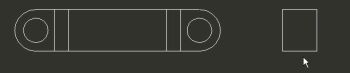
- Select the ENGINE_COMPONENTS.DRW in the browser to view its preview.
- Click Next Sheet
 , then click Open in Pro/E .
- Notice the drawing opens directly to Sheet 2.
- Place the cursor between the FRONT and TOP views.
- Press CTRL, press and hold the middle mouse button, and move the mouse towards you to zoom in on the views.
- Notice that the drawing views and the dimensions have updated to the new length of 30.
 Updated Drawing |
- Select the 30 dimension. Then double-click on the 30 value, type 33, and press ENTER.
- Click Regenerate from the main toolbar.
- Notice that the drawing views and the dimensions update.
- Click Window > CONNECTING_ROD_COMPLETE.PRT to view the part.
- Double-click on the main body of the model to view the dimensions for EXTRUDE 1.
- Notice the feature has updated to the latest value of 33.
-
Click File > Close Window twice to close both windows.
| Task 5-5. (OPTIONAL) Re-check the Interference on the top level assembly. |
- Select the Folder Browser , and select the ProE_models folder.
- Select the AC‑40.ASM in the browser to view its preview.
- Click Open in Pro/E .
- Click Drag Component from the main toolbar.
- Select any blade on the impeller and drag the mechanism.
- Middle-click when finished dragging
- Run the mechanism and view any interference, as shown in the following figure:
- Click Applications > Mechanism from the main menu.
- Click Run Analysis from the Mechanism Toolbar.
- Select RUN_ENGINE and click Run. Click Close from the Analyses dialog box.
- Click Replay Analysis from the Mechanism Toolbar.
- Select Global Interference and click Play from the Playbacks dialog box. (The interference will take a few seconds to calculate).
- Drag the Speed slider to maximum, and click Play from the Animate dialog box.
- Notice no interference is present.
 No Interference Detected |
- Click Stop when finished viewing the animation, and then click Close > Close.
- Click Applications > Standard from the main menu. Click Yes from the message window
- Click Save and then click OK.
This completes the fifth exercise.
CONGRATULATIONS !
You have completed the introductory Hands-On Workshop tutorial.
SUMMARY
Now that you have completed this tutorial you should be able to:
- Describe Pro/ENGINEER Wildfire fundamentals.
- Navigate the Pro/ENGINEER Wildfire interface.
- Preview, open, and orient design models.
- Create basic part models.
- Create an assembly.
- Run a simple mechanism.
- Create a drawing with views of an assembly and a part.
- Show and manipulate dimensions on drawing views.
- Modify a model and observe the assembly and drawing update.
- Check for assembly interferences.
Want to take best-in-class Pro/ENGINEER training without the inconvenience and expense of travel?
It easy � just join PTC University! PTC University is an online portal that combines the depth and breadth of PTC�s traditional training programs with the convenience, flexibility, and affordability of distance learning.
With PTC University, you have access to the most effective forms of distance learning including Virtual Classes, Web-based Training, e-Knowledge Assets, and Communities of Practice.
Whether you want to polish your existing skills or learn a new technique, PTC University will give you the right information, at the right time, with right media - without ever having to leave the comfort of your desk.
Learn more on how PTC University can help you improve your product development practices at www.ptc.com/go/learning.
Copyright � 2004 Parametric Technology Corporation. All Rights Reserved.
User and training documentation from Parametric Technology Corporation (PTC) is subject to the copyright laws of the United States and other countries and is provided under a license agreement that restricts copying, disclosure, and use of such documentation. PTC hereby grants to the licensed user the right to make copies in printed form of this documentation if provided on software media, but only for internal/personal use and in accordance with the license agreement under which the applicable software is licensed. Any copy made shall include the PTC copyright notice and any other proprietary notice provided by PTC. This documentation may not be disclosed, transferred, modified, or reduced to any form, including electronic media, or transmitted or made publicly available by any means without the prior written consent of PTC and no authorization is granted to make copies for such purposes.
Information described herein is furnished for general information only, is subject to change without notice, and should not be construed as a warranty or commitment by PTC. PTC assumes no responsibility or liability for any errors or inaccuracies that may appear in this document.
The software described in this document is provided under written license agreement, contains valuable trade secrets and proprietary information, and is protected by the copyright laws of the United States and other countries. It may not be copied or distributed in any form or medium, disclosed to third parties, or used in any manner not provided for in the software licenses agreement except with written prior approval from PTC. UNAUTHORIZED USE OF SOFTWARE OR ITS DOCUMENTATION CAN RESULT IN CIVIL DAMAGES AND CRIMINAL PROSECUTION.
Parametric Technology Corporation, 140 Kendrick Street, Needham, MA 02494 USA
Registered Trademarks of Parametric Technology Corporation or a Subsidiary
Advanced Surface Design, Behavioral Modeling, CADDS, Computervision, CounterPart, EPD, EPD.Connect, Expert Machinist, Flexible Engineering, GRANITE, HARNESSDESIGN, Info*Engine, InPart, MECHANICA, Optegra, Parametric Technology, Parametric Technology Corporation, PartSpeak, PHOTORENDER, Pro/DESKTOP, Pro/E, Pro/ENGINEER, Pro/HELP, Pro/INTRALINK, Pro/MECHANICA, Pro/TOOLKIT, Product First, PTC, the PTC logo, PT/Products, Shaping Innovation, and Windchill.
Trademarks of Parametric Technology Corporation or a Subsidiary
3DPAINT, Associative Topology Bus, AutobuildZ, CDRS, Create Collaborate Control, CV, CVact, CVaec, CVdesign, CV-DORS, CVMAC, CVNC, CVToolmaker, DataDoctor, DesignSuite, DIMENSION III, DIVISION, e/ENGINEER, eNC Explorer, Expert MoldBase, Expert Toolmaker, ISSM, KDiP, Knowledge Discipline in Practice, Knowledge System Driver, ModelCHECK, MoldShop, NC Builder, Pro/ANIMATE, Pro/ASSEMBLY, Pro/CABLING, Pro/CASTING, Pro/CDT, Pro/CMM, Pro/COLLABORATE, Pro/COMPOSITE, Pro/CONCEPT, Pro/CONVERT, Pro/DATA for PDGS, Pro/DESIGNER, Pro/DETAIL, Pro/DIAGRAM, Pro/DIEFACE, Pro/DRAW, Pro/ECAD, Pro/ENGINE, Pro/FEATURE, Pro/FEM-POST, Pro/FICIENCY, Pro/FLY-THROUGH, Pro/HARNESS, Pro/INTERFACE, Pro/LANGUAGE, Pro/LEGACY, Pro/LIBRARYACCESS, Pro/MESH, Pro/Model.View, Pro/MOLDESIGN, Pro/NC-ADVANCED, Pro/NC-CHECK, Pro/NCMILL, Pro/NCPOST, Pro/NC-SHEETMETAL, Pro/NC-TURN, Pro/NC-WEDM, Pro/NC-Wire EDM, Pro/NETWORK ANIMATOR, Pro/NOTEBOOK, Pro/PDM, Pro/PHOTORENDER, Pro/PIPING, Pro/PLASTIC ADVISOR, Pro/PLOT, Pro/POWER DESIGN, Pro/PROCESS, Pro/REPORT, Pro/REVIEW, Pro/SCAN-TOOLS, Pro/SHEETMETAL, Pro/SURFACE, Pro/VERIFY, Pro/Web.Link, Pro/Web.Publish, Pro/WELDING, Product Development Means Business, ProductView, PTC Precision, Shrinkwrap, Simple Powerful Connected, The Product Development Company, The Way to Product First, Wildfire, Windchill DynamicDesignLink, Windchill PartsLink, Windchill PDMLink, Windchill ProjectLink, and Windchill SupplyLink.
Patents of Parametric Technology Corporation or a Subsidiary
Additional foreign equivalents may be issued or pending � contact PTC for further information:
Registration No. Issue Date
6,665,569 B1 16-December-2003
6,625,607 B1 23-September-2003
6,580,428 B1 17-June-2003
GB2354684B 02-July-2003
GB2384125 15-October-2003
GB2354096 12-November-2003
6,608,623 B1 19 August 2003
GB2353376 05-November-2003
GB2354686 15-October-2003
6,545,671 B1 08-April-2003
GB2354685B 18-June-2003
6,608,623 B1 19 August-2003
6,473,673 B1 29-October-2002
GB2354683B 04-June-2003
6,447,223 B1 10-Sept-2002
6,308,144 23-October-2001
5,680,523 21-October-1997
5,838,331 17-November-1998
4,956,771 11-September-1990
5,058,000 15-October-1991
5,140,321 18-August-1992
5,423,023 05-June-1990
4,310,615 21-December-1998
4,310,614 30-April-1996
4,310,614 22-April-1999
5,297,053 22-March-1994
5,513,316 30-April-1996
5,689,711 18-November-1997
5,506,950 09-April-1996
5,428,772 27-June-1995
5,850,535 15-December-1998
5,557,176 09-November-1996
5,561,747 01-October-1996
Third-Party Trademarks
Adobe is a registered trademark of Adobe Systems. Advanced ClusterProven, ClusterProven, and the ClusterProven design are trademarks or registered trademarks of International Business Machines Corporation in the United States and other countries and are used under license. IBM Corporation does not warrant and is not responsible for the operation of this software product. AIX is a registered trademark of IBM Corporation. Allegro, Cadence, and Concept are registered trademarks of Cadence Design Systems, Inc. Apple, Mac, Mac OS, and Panther are trademarks or registered trademarks of Apple Computer, Inc. AutoCAD and Autodesk Inventor are registered trademarks of Autodesk, Inc. Baan is a registered trademark of Baan Company. CADAM and CATIA are registered trademarks of Dassault Systemes. COACH is a trademark of CADTRAIN, Inc. DOORS is a registered trademark of Telelogic AB. FLEXlm is a trademark of Macrovision Corporation. Geomagic is a registered trademark of Raindrop Geomagic, Inc. EVERSYNC, GROOVE, GROOVEFEST, GROOVE.NET, GROOVE NETWORKS, iGROOVE, PEERWARE, and the interlocking circles logo are trademarks of Groove Networks, Inc. Helix is a trademark of Microcadam, Inc. HOOPS is a trademark of Tech Soft America, Inc. HP-UX is a registered trademark and Tru64 is a trademark of the Hewlett-Packard Company. I-DEAS, Metaphase, Parasolid, SHERPA, Solid Edge, and Unigraphics are trademarks or registered trademarks of Electronic Data Systems Corporation (EDS). InstallShield is a registered trademark and service mark of InstallShield Software Corporation in the United States and/or other countries. Intel is a registered trademark of Intel Corporation. IRIX is a registered trademark of Silicon Graphics, Inc. LINUX is a registered trademark of Linus Torvalds, MatrixOne is a trademark of MatrixOne, Inc. Mentor Graphics and Board Station are registered trademarks and 3D Design, AMPLE, and Design Manager are trademarks of Mentor Graphics Corporation. MEDUSA and STHENO are trademarks of CAD Schroer GmbH. Microsoft, Microsoft Project, Windows, the Windows logo, Windows NT, Visual Basic, and the Visual Basic logo are registered trademarks of Microsoft Corporation in the United States and/or other countries. Netscape and the Netscape N and Ship's Wheel logos are registered trademarks of Netscape Communications Corporation in the U.S. and other countries. Oracle is a registered trademark of Oracle Corporation. OrbixWeb is a registered trademark of IONA Technologies PLC. PDGS is a registered trademark of Ford Motor Company. RAND is a trademark of RAND Worldwide. Rational Rose is a registered trademark of Rational Software Corporation. RetrievalWare is a registered trademark of Convera Corporation. RosettaNet is a trademark and Partner Interface Process and PIP are registered trademarks of �RosettaNet,� a nonprofit organization. SAP and R/3 are registered trademarks of SAP AG Germany. SolidWorks is a registered trademark of SolidWorks Corporation. All SPARC trademarks are used under license and are trademarks or registered trademarks of SPARC International, Inc. in the United States and in other countries. Products bearing SPARC trademarks are based upon an architecture developed by Sun Microsystems, Inc. Sun, Sun Microsystems, the Sun logo, Solaris, UltraSPARC, Java and all Java based marks, and �The Network is the Computer� are trademarks or registered trademarks of Sun Microsystems, Inc. in the United States and in other countries. TIBCO, TIBCO Software, TIBCO ActiveEnterprise, TIBCO Designer, TIBCO Enterprise for JMS, TIBCO Rendezvous, TIBCO Turbo XML, TIBCO BusinessWorks are the trademarks or registered trademarks of TIBCO Software Inc. in the United States and other countries. WebEx is a trademark of WebEx Communications, Inc.
Third-Party Technology Information
Certain PTC software products contain licensed third-party technology: Rational Rose 2000E is copyrighted software of Rational Software Corporation. RetrievalWare is copyrighted software of Convera Corporation. VisTools library is copyrighted software of Visual Kinematics, Inc. (VKI) containing confidential trade secret information belonging to VKI. HOOPS graphics system is a proprietary software product of, and is copyrighted by, Tech Soft America, Inc. G-POST is copyrighted software and a registered trademark of Intercim. VERICUT is copyrighted software and a registered trademark of CGTech. Pro/PLASTIC ADVISOR is powered by Moldflow technology. Moldflow is a registered trademark of Moldflow Corporation. The JPEG image output in the Pro/Web.Publish module is based in part on the work of the independent JPEG Group. DFORMD.DLL is copyrighted software from Compaq Computer Corporation and may not be distributed. METIS, developed by George Karypis and Vipin Kumar at the University of Minnesota, can be researched at http://www.cs.umn.edu/~karypis/metis. METIS is � 1997 Regents of the University of Minnesota. LightWork Libraries are copyrighted by LightWork Design 1990�2001. Visual Basic for Applications and Internet Explorer is copyrighted software of Microsoft Corporation. Adobe Acrobat Reader is copyrighted software of Adobe Systems. Parasolid � Electronic Data Systems (EDS). Windchill Info*Engine Server contains IBM XML Parser for Java Edition and the IBM Lotus XSL Edition. Pop-up calendar components Copyright � 1998 Netscape Communications Corporation. All Rights Reserved. TECHNOMATIX is copyrighted software and contains proprietary information of Technomatix Technologies Ltd. TIBCO ActiveEnterprise, TIBCO Designer, TIBCO Enterprise for JMS, TIBCO Rendezvous, TIBCO Turbo XML, TIBCO BusinessWorks are provided by TIBCO Software Inc. Technology "Powered by Groove" is provided by Groove Networks, Inc. Technology "Powered by WebEx" is provided by WebEx Communications, Inc. Oracle 8i run-time and Oracle 9i run-time, Copyright 2002�2003 Oracle Corporation. Oracle programs provided herein are subject to a restricted use license and can only be used in conjuction with the PTC software they are provided with.
Apache Server, Tomcat, Xalan, and Xerces are technologies developed by, and are copyrighted software of, the Apache Software Foundation (http://www.apache.org/) � their use is subject to the terms and limitations at: http://www.apache.org/LICENSE.txt.
Acrobat Reader is copyrighted software of Adobe Systems Inc. and is subject to the Adobe End-User License Agreement as provided by Adobe with those products.
UnZip (� 1990-2001 Info-ZIP, All Rights Reserved) is provided �AS IS� and WITHOUT WARRANTY OF ANY KIND. For the complete Info ZIP license see ftp://ftp.info-zip.org/pub/infozip/license.html. Gecko and Mozilla components are subject to the Mozilla Public License Version 1.1 at http://www.mozilla.org/MPL/. Software distributed under the MPL is distributed on an "AS IS" basis, WITHOUT WARRANTY OF ANY KIND, either express or implied. See the MPL for the specific language governing rights and limitations.
The Java� Telnet Applet (StatusPeer.java, TelnetIO.java, TelnetWrapper.java, timedOutException.java), Copyright � 1996, 97 Mattias L. Jugel, Marcus Mei�ner, is redistributed under the GNU General Public License. This license is from the original copyright holder and the Applet is provided WITHOUT WARRANTY OF ANY KIND. You may obtain a copy of the source code for the Applet at http://www.mud.de/se/jta (for a charge of no more than the cost of physically performing the source distribution), by sending e-mail to [email protected] or [email protected]�you are allowed to choose either distribution method. The source code is likewise provided under the GNU General Public License.
GTK+The GIMP Toolkit are licensed under the GNU LGPL. You may obtain a copy of the source code at http://www.gtk.org/, which is likewise provided under the GNU LGPL. zlib software Copyright � 1995-2002 Jean-loup Gailly and Mark Adler.
OmniORB is distributed under the terms and conditions of the and GNU Library General Public License. The Java Getopt.jar, copyright 1987-1997 Free Software Foundation, Inc.; Java Port copyright 1998 by Aaron M. Renn ([email protected]), is redistributed under the GNU LGPL. You may obtain a copy of the source code at: http://www.urbanophile.com/arenn/hacking/download.html The source code is likewise provided under the GNU LGPL.
This product may include software developed by the OpenSSL Project for use in the OpenSSL Toolkit. (http://www.openssl.org/): Copyright (c) 1998-2003 The OpenSSL Project. All rights reserved. This product may include cryptographic software written by Eric Young ([email protected]).
Mozilla Japanese localization components are subject to the Netscape Public License Version 1.1 (at http://www.mozilla.org/NPL/). Software distributed under NPL is distributed on an "AS IS" basis, WITHOUT WARRANTY OF ANY KIND, either express or implied (see the NPL for the specific language governing rights and limitations). The Original Code is Mozilla Communicator client code, released March 31, 1998 and the Initial Developer of the Original Code is Netscape Communications Corporation. Portions created by Netscape are Copyright (c) 1998 Netscape Communications Corporation. All Rights Reserved. Contributor(s): Kazu Yamamoto ; Ryoichi Furukawa ; Tsukasa Maruyama ; Teiji Matsuba
UNITED STATES GOVERNMENT RESTRICTED RIGHTS LEGEND
This document and the software described herein are Commercial Computer Documentation and Software, pursuant to FAR 12.212(a)-(b) (OCT�95) or DFARS 227.7202-1(a) and 227.7202-3(a) (JUN�95), is provided to the US Government under a limited commercial license only. For procurements predating the above clauses, use, duplication, or disclosure by the Government is subject to the restrictions set forth in subparagraph (c)(1)(ii) of the Rights in Technical Data and Computer Software Clause at DFARS 252.227-7013 (OCT�88) or Commercial Computer Software-Restricted Rights at FAR 52.227-19(c)(1)-(2) (JUN�87), as applicable.
Parametric Technology Corporation, 140 Kendrick Street, Needham, MA 02494 USA