Advanced Hands-On Workshop Tutorial
Pro/ENGINEER Wildfire 2.0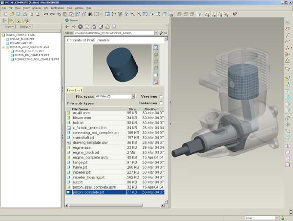
Before you get started
This tutorial is intended to be used alongside Pro/ENGINEER Wildfire 2.0.
- Please make sure that Pro/ENGINEER Wildfire 2.0 is installed on your machine before continuing.
- If Pro/ENGINEER is already running, please exit it now.
You will need to create a special startup command for Pro/ENGINEER, and install the Pro/ENGINEER model files for this Tutorial:
- Download the model files from www.ptc.com/go/handson/models. Save the zip file to your desktop.
- Extract the zip file to a location on your hard drive.
- A plain drive letter (ex: C:\ ) is recommended, and is used for this tutorial.
- Browse to the folder created by the zip file.
- For example: C:\users\student\HOW_ADV-WF2
- Assuming Pro/ENGINEER Wildfire 2.0 is already installed on your computer, locate the shortcut from the Start menu.
- Right-click the shortcut and select Copy.
- Right-click on your desktop and select Paste Shortcut.
- Right-click newly pasted shortcut and select Properties.
- Enter (or paste in) the full path to the Intro_HOW folder.
- For example: C:\users\student\HOW_ADV-WF2
- Start Pro/ENGINEER Wildfire 2.0 using the newly configured shortcut.
Using this Tutorial
- Carefully read all of the content on each page and perform the given steps before proceeding to the next page.
- You will see various icons throughout the tutorial:
 Information is provided at the start of most tasks.
 Tips are provided along the way.
 Notes are provided as additional information.
- There are several conventions used when working with Pro/ENGINEER Wildfire 2.0:
- The "picks and clicks" are shown in Bold.
- Text that you enter is shown in Bold.
- Icons and their names are shown inline with the text.
- Names of models are shown in CAPS.
- Keyboard keys are shown in CAPS.
Welcome
Welcome to the Advanced Hands-On Workshop Tutorial for Pro/ENGINEER Wildfire 2.0. In this tutorial you will learn how to quickly ramp-up from Pro/ENGINEER 2001 directly to Pro/ENGINEER Wildfire 2.0. This tutorial is designed for students who have experience with older releases of Pro/ENGINEER
.Contents
- Pro/ENGINEER Wildfire 2.0 Concepts and Interface
- Learn Pro/ENGINEER Wildfire 2.0 concepts and interface changes.
- Exercise 1: Opening, Orienting, and Editing Models
- Preview and Open Models.
- Use new orientation tools to spin, pan, and zoom.
- Select components and features using various techniques.
- Hide / Unhide components and features.
- Delete and edit features.
- Redefine features using the dashboard.
- Exercise 2: Creating Part Models
- Create datum axes and planes.
- Create holes, rounds, chamfers, and shells.
- Created extrude, revolve, and rib features.
- Copy, mirror, and pattern features.
- Exercise 3: Creating Assemblies
- Drag assembled components using Drag Component.
- Drag components during assembly using CTRL + ALT + Left Mouse Button.
- Convert constraints into connections.
- Setup and utilize component interfaces.
- Exercise 4: Creating Drawings
- Use the Drawing View dialog box.
- Undo and Redo actions in drawings.
- Use the Pause Show and Erase option.
|
|
Concepts and Interface Section Read through the 7 pages in this section to learn about the major Pro/ENGINEER Wildfire 2.0 enhancement themes before starting the first exercise. |
Pro/ENGINEER Wildfire 2.0 Overview
With the release of Pro/ENGINEER Wildfire and Pro/ENGINEER Wildfire 2.0, there have been many productivity and functionality improvements from Pro/ENGINEER 2001. These include a new user interface, a consolidated set of feature tools, and the ability to interact directly with models and features.
The Pro/ENGINEER Wildfire 2.0 user interface includes integrated web and folder browsers, providing easy access to design information and model data. Pro/ENGINEER Wildfire feature tools utilize a dashboard interface, providing simple and intuitive access to options for creating and editing features.
Modifying models is made easier through the use of drag handles that enable dynamic modifying of model geometry, and the new undo/redo tool enables reversing of operations such as deleting and editing features.
There are many enhancements to feature editing tools, including several new patterning options, and new tools for quickly and dynamically grouping, copying and pasting features.
Creating drawings has been made easier using a single new drawing view dialog box that consolidates all drawing view options.
Pro/ENGINEER Wildfire 2.0 Concepts
Three of the concepts employed over much of Pro/ENGINEER Wildfire 2.0 are:
- Focus on the Model
- Consolidated Feature Tools
- Design Collaboration Tools
 Pro/ENGINEER Wildfire 2.0 Interface |
Focus on the Model
- Large Graphics Area- Pro/ENGINEER Wildfire 2.0 window can be maximized, and the model tree and browser can be minimized to produce a large working area.
- Gray Background- Subdued gray background allows the model to stand out.
- Dynamic Feature Preview- Features can be manipulated in real time, while the yellow dynamic preview updates.
- Direct Feature Manipulation- Many feature operations while creating or editing features can be done on the model through a series of drag handles and right-click options.
Consolidated Feature Tools
- Feature Tools- Each of the easy-to-use feature tools combines several traditional features into a series of dashboard-driven tools.
- Flexible Workflow- In many cases you can select an item, and then start a tool, or you can start a tool and then select an item.
- Simple First- The feature tools immediately present you with the common options for creating features. However, advanced options are readily available.
- Consistency- The feature tools that use the Dashboard all work very similar to each other.
Design Collaboration Tools
- Embedded Web Browser- The browser panel may be expanded or collapsed at any time from the left side of the graphics window. Browse to a vendors web site and drag and drop a model into the graphics window, or browse to other applications such as Windchill ProjectLink.
- Dynamic Conferencing- Start a Design Collaboration Session in which you can collaborate using Pro/ENGINEER Wildfire 2.0 in real time with colleagues in other locations.
Pro/ENGINEER Wildfire 2.0 Interface
There are 3 important components of the main Pro/ENGINEER Wildfire 2.0 interface:
- Navigator
- Web Browser
- Main Interface
 Pro/ENGINEER Wildfire 2.0 interface |
Navigator
- Folder Navigator (left of the screen)
- Allows you to browse folders on your machine.
- A collapsible panel.
Web Browser
- File List & Preview Window (middle of the screen)
- Select a folder in the Folder Navigator to view its contents.
- Select a model to preview it.
- A collapsible panel.
- Browse Internet
- You can also use the browser to view web sites or html pages.
Main Interface
- Graphics Window (gray portion of screen)
- Create Parts, assembles, and drawings in this window.
- Main Menu (top of the screen)
- This pull-down menu has common menu options such as File, Edit, Insert, Tools, and Help.
- Main Toolbar (top of the screen)
- A toolbar containing common file, undo/redo, and viewing icons.
- Feature Toolbar (right of the screen)
- A toolbar containing icons to start feature tools.
Pro/ENGINEER Wildfire 2.0 Interface (continued)
The following figure shows additional interface components:
Navigator
- Model Tree (left of the screen)
- Displays in place of the folder browser when a model is open.
- A collapsible panel
Web Browser
- Collapsed in this view
Main Interface
- Graphics Window (center of the screen)
- New gradient gray background.
- Yellow dynamic preview on model.
- Can collapse model tree and maximize window to create large working area.
- Dashboard (bottom of the screen)
- A dialog bar for creating/redefining features
- Menu Manager (right of the screen)
- Not shown by default
 Pro/ENGINEER Wildfire 2.0 interface |
|
|
Consolidated Feature Tools Many of the traditional menu-based features have been consolidated into new feature tools. These icons can be found in the Feature toolbar on the right of the screen. |
The following tools are used when creating initial model features:
| NAME |
ICON |
Previous Command(s) |
| Extrude |
|
Extruded protrusion, cut, surface, surface trim. Solid and thin. |
| Revolve |
|
Revolved protrusion, cut, surface, surface trim. Solid and thin. |
| Variable Section Sweep |
|
Variable Section Swept protrusion, cut, surface, surface trim. Solid and thin |
| Boundary Blend |
|
Surface by Boundaries |
| Style |
|
Style Feature |
The following tools are used when creating secondary model features:
| NAME |
ICON |
Previous Command(s) |
| Hole |
|
Hole (all types) |
| Shell |
|
Shell |
| Rib |
|
Rib |
| Draft |
|
Draft (all types) |
| Round |
|
Simple and Advanced Rounds |
| Chamfer |
|
Edge Chamfer |
|
|
Notice these icons are all cyan in color. |
|
|
Consolidated Feature Tools (continued) Many of the traditional menu-based features have been consolidated into new feature tools. |
The following tools are found in the Main toolbar:
| NAME |
ICON |
Previous Command(s) |
| Copy & Paste |
|
Copy solid features and groups using Same Refs |
| Copy & Paste Special |
|
Copy solid features and groups using New Refs or Move (Rotate and Translate). |
The following tools are found in the Edit menu:
| NAME |
ICON |
Previous Command(s) |
| Mirror |
|
Feature Copy Mirror, Mirror Geometry, Surface Transform Mirror |
| Pattern |
|
Identical, Varying, and General Patterns. Pattern Tables. |
| Project |
|
Projected Curve |
| Wrap |
|
Formed Curve |
| Trim |
|
Surface Trim- Use Quilt. |
| Extend | Surface Extend | |
| Intersect | 2 Projections curve, Intersect curve | |
| Merge | Surface Merge | |
| Fill | Flat Surface | |
| Offset |
Curve Offset from Surface, from Curve, from Boundary | |
| Thicken | Thin Protrusion- Use Quilt Thin Cut- Use Quilt | |
| Solidify |
|
Solid Protrusion, Use Quilt Solid Cut, Use Quilt Patch |
|
|
Notice all the Editing icons are magenta in color. |
|
|
Consolidated Feature Tools (continued) Many of the traditional menu-based features have been consolidated into new feature tools. |
The following tools can be found in the Feature toolbar on the right of the screen.
| NAME |
ICON |
Previous Command(s) |
| Sketch Tool |
|
Sketched datum curve. |
| Datum Curve |
|
Datum curve through points, from file, use X-sec, by equation. |
| Datum Plane |
|
All Datum Plane options |
| Datum Axis |
|
All Datum Axis options |
| Datum Points | |
All Datum Point options |
| Datum Csys | All Datum Csys options |
|
|
Notice the Datum tools are all brown in color. (A Sketch is not considered a datum feature) |
| Exercise 1: Opening, Orienting, and Editing Models. |
Objectives
After successfully completing this exercise, you will know how to:
- Preview and Open Models.
- Use new orientation tools to spin, pan, and zoom.
- Select components and features using various techniques.
- Hide / Unhide components and features.
- Delete and edit features.
- Redefine features using the dashboard.
|
|
Pro/ENGINEER Wildfire 2.0 Resource Center The Pro/ENGINEER Wildfire 2.0 Resource Center (also known as the 'home page'), includes interactive tours, tutorials, and quick reference material on Pro/ENGINEER Wildfire. There is also a 'menu mapper' tool to translate menu options from previous releases to Pro/ENGINEER Wildfire 2.0. |
| Task 1-1. Start Pro/ENGINEER Wildfire and observe the integrated Web browser. |
- Start Pro/ENGINEER Wildfire 2.0.
- Notice the integrated Web browser displays the Pro/ENGINEER Wildfire 2.0 home page by default.
 Home Page |
|
|
You can return to this home page by clicking Home You also can customize the home page using a config option, as well as save commonly used pages as favorites. |
|
|
Folder Browser and File List You can browse folders and set the working directory using the Folder Browser. Once a folder is selected, the File List displays in the browser, where you can select files to preview and open. |
| Task 1-2. Browse the folder structure and preview models. |
- In the Folder Browser
 , locate the HOW_ADV-WF2 folder, and expand it by clicking the '+'.
- Click on the Part_Modeling folder to view the contents of the folder in the browser.
- Right-click on the Part_Modeling folder and select Set Working Directory.
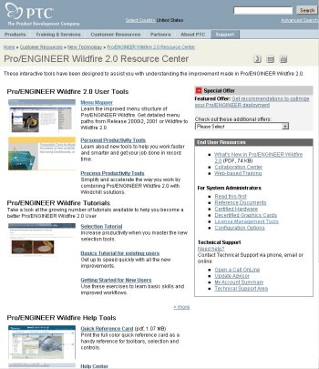
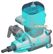
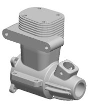
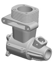
- Preview models in the preview window as shown in the following figure:
- Select the ENGINE_BLOCK.PRT from the File List.
- Select the ENGINE.ASM from the File List.
- Middle-click and drag in the preview window to spin the model.
 
Preview of the ENGINE_BLOCK and ENGINE |
|
|
You can also Pan and Zoom in the preview window. |
|
|
Spin Use the Middle Mouse button to Spin the model. |
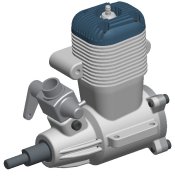
| Task 1-3. Open the ENGINE.ASM and Spin using the mouse. |
- With ENGINE.ASM visible in the preview window, click Open in Pro/E
 from the browser.
 ENGINE.ASM |
- Middle-drag in the graphics window to spin the model.
- Spin the model in several directions.
- Notice that the model is spinning around the `spin center' in the center of the model.
- Click Saved View List
 from the main toolbar and select Standard Orientation.
- Click Spin Center
 from the main toolbar to disable it.
- Place the mouse cursor on the top of the model, and middle-drag to spin.
- Place the mouse cursor on the bottom of the model, and middle-drag to spin.
- Notice the mouse cursor position is now the center of rotation.
|
|
Zoom Use CTRL + Middle Mouse button, while dragging vertically to Zoom in/out. |
| Task 1-4. Zoom in and out using the mouse. |
- Click Saved View List from the main toolbar and select Standard Orientation.
- Click Spin Center from the main toolbar to enable it.
- Place the cursor over a bolt in the model as shown in the following figure.
- Press CTRL + middle-drag vertically towards you to zoom in.
- Press CTRL + middle-drag vertically away from you to zoom out.
 Zoomed in on a Bolt |
- If you have a wheel mouse, roll the mouse wheel towards you to zoom in.
- Roll the mouse wheel away from you to zoom out.
|
|
Place the cursor over objects of interest before zooming in. |
|
|
Pan Use SHIFT + Middle Mouse button to Pan the model. |
| Task 1-5. Pan the model using the mouse. |
- Press SHIFT + middle-drag to pan the model in the graphics window.
- Press CTRL + D as a shortcut to return to the Standard Orientation.
- Move the mouse cursor over ENGINE.ASM, and press CTRL + middle-drag horizontally to turn the model right or left.
- Click View > Orientation > Previous from the main menu.
- Click Orient Mode
 from the main toolbar to enable it.
- Move the cursor over the components in the assembly.
- Notice now the assembly components no longer highlight.
|
|
In addition to being able to Spin, Pan, and Zoom without highlighting, Orient Mode |
- Click Saved View List from the main toolbar and select 3D1.
- Notice that Orient Mode is now disabled in the main toolbar.
|
|
Selecting Items Use the Left Mouse button to select. Press CTRL and select with the Left Mouse Button to select multiple items. De-select a single item by pressing CTRL and selecting it again. Deselect all items by selecting on the background. |
| Task 1-6. Select components from the model tree. |
- Click View > Display Settings > Model Display from the main menu.
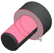
- Select the Shade tab and disable Transparency.
- Click OK from the Model Display dialog box.
  Transparency Disabled |
-
Select CRANKSHAFT.PRT in the model tree.
- Expand PISTON_ASSY.ASM, then press CTRL and select PISTON.PRT and CONNECTING_ROD.PRT.
- Note where each component is in the model.
- Click in the graphics window background to de-select all components.
|
|
Query Select Right-click to query until highlighted (cyan). Left-click to select (red). |
| Task 1-7. Select components from the model directly using Query Select. |
- Cursor over CONNECTING_ROD.PRT in the model, right-click to query until the component highlights, and then click to select it. (leave the component selected)
  Query and Select the CONNECTING_ROD.PRT |
- Cursor over PISTON.PRT.
- Press CTRL and right-click to query until the component highlights, and then click to select it.
- Two components should now be selected.
- Click in the graphics window to de-select all components.
|
|
Selecting Items From a List The Pick From List option allows you to select from a text list. Press and hold the right mouse button briefly to activate popup menus such as Pick From List. |
| Task 1-8. Select components from the model using Pick From List. |
- Place the cursor over CONNECTING_ROD.PRT, right-click and hold, and then select Pick From List.
- Select CONNECTING_ROD.PRT from the Pick From List dialog box and click OK.
 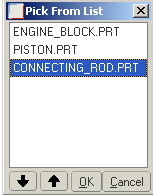 Selecting CONNECTING_ROD.PRT |
- Cursor over CRANKSHAFT.PRT and select it. This selection has replaced the previous one.
- Click in the graphics window to de-select all components.
|
|
Repainting the screen does not de-select items. |
|
|
Using the Search Tool The Search Tool provides an easy way to select items that are not visible, or multiple items based on a search rule. |
| Task 1-9. Use the Search Tool and Hide and Unhide components. |
- Start the Search Tool
 from the main toolbar.
- Select Component as the Look For option.
- Edit the Criteria Value to ENG* and click Find Now.
- Press CTRL + A to select all 3 items and click Add Item
 .
.
- Click Close from the Search Tool dialog, and notice the components are selected.
- Right-click hold, then select Hide.
 Components Hidden |
- Press CTRL and select the ENGINE_BLOCK.PRT, ENGINE_HEAD.PRT, and ENGINE_COVER.PRT from the model tree.
- Right-click, and select Unhide.
- Click in the graphics window to de-select all components.
|
|
In order to save the current Hide/Unhide status when the model is saved, you must click View > Visibility > Save Status. |
|
|
Feature Level Undo/Redo You can Undo and Redo many common feature operations, such as Edit, Edit Definition, Suppress, and Delete. |
| Task 1-10. Open ENGINE_BLOCK.prt and select features. |
|
|
IMPORTANT- In the next step, you will be opening a second Pro/ENGINEER window. You must resize and reposition the window to the right of the tutorial. |
- Select ENGINE_BLOCK.prt from the assembly model.
- Right-click and hold, and notice the many options available, then select Open.
- Press CTRL, and select EXH_MOUNT, BORE, and the CARB_MOUNT group from the model tree.
- De-select the features by clicking in the graphics window.
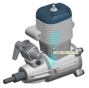
- Cursor over the BORE feature and select it from the model as shown in the following figure.
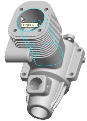  Highlight and select the BORE feature from the Model |
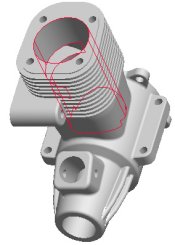
- Orient the model as shown in the following figure, then right-click and select Delete.
- Click OK to delete the child features.
- Click Undo
 from the main toolbar.
|
|
You can also press CTRL + Z for Undo |
  Deleting Features and Clicking Undo |
|
|
Query selection of features from a part works the same as previously demonstrated with components in an assembly. |
- Click File > Close Window
 from the main menu to return to the ENGINE.ASM
|
|
Editing Dimensions When using Edit, you can enter dimension values for a feature in the graphics window. |
|
Task 1-11. Redefine an extruded protrusion on the CONNECTING_ROD.PRT. |
|
|
IMPORTANT- In the next step, you will be opening a second Pro/ENGINEER window. You must resize and reposition the window to the right of the tutorial. |
- With the ENGINE.ASM open, select the CONNECTING_ROD.PRT using any method you wish.
- Right-click and select Open.
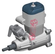
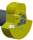
- Edit the model as shown in the following figure:
- Select the RIGHT_END protrusion from the model tree, right-click and select Edit.
- Double-click on the 5 dimension and enter 10.
- Click Regenerate
 from the main toolbar to update the model.
- Notice the LEFT_END protrusion updates since RIGHT_END is one of its parents.
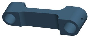 Editing the CONNECTING_ROD.PRT |
|
|
You can also select from the "Most Recently Used" drop-down list when editing dimensions. |
|
|
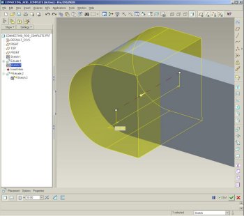
Redefining Features You can use the Edit Definition option to redefine features. When redefining a feature, you have access to the Dashboard for that feature, as well as drag handles and right-click options on the dynamic feature preview. |
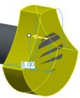
| Task 1-12. Redefine an extruded protrusion on the CONNECTING_ROD.PRT. |
-
Select the RIGHT_END feature from the model.
- Right-click, and select Edit Definition.
- Notice that any features created after this extrude are not displayed.
- Notice that the depth is set to Both Sides
 in the dashboard.
- Enter 8 for the depth in the dashboard.
- Drag the depth handle from 8 to 12. Notice the depth value has updated in the dashboard.
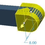 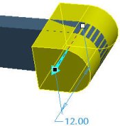 Dragging Depth Handle |
-
Click Undo from the main toolbar to return to a depth of 8.
- Click Redo
 from the main toolbar to return to a depth of 12.
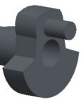
- Click Complete Feature
 from the dashboard. The model regenerates.
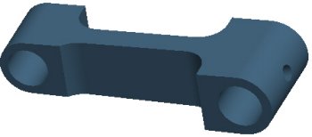 Model Regenerated |
|
|
Redefining Features Changing feature options, such as Depth can be quickly defined using Dashboard icons or by right-clicking on the depth handle. |
| Task 1-13. Redefine a second extruded protrusion. |
- Redefine the LEFT_END feature as shown in the following figure:
- Select the LEFT_END protrusion from the model tree.
- Right-click, and select Edit Definition.
- Select the Options tab from the dashboard.
- Specify To Selected for Side 1, and then select the front surface of the RIGHT_END protrusion as shown.
- Click Complete Feature from the dashboard.
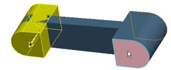 Figure 13: Redefining Depth |
|
|
Regenerating Models In addition to using the toolbar icon, you can also press CTRL + G as a shortcut to Regenerate. |
| Task 1-14. Edit the depth of the RIGHT_END and observe the LEFT_END update. |
- Select the RIGHT_END protrusion from the model, right-click and select Edit.
- Double-click on the 12 dimension and enter 7.
- Press CTRL + G to regenerate the model.
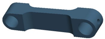 Figure 14: Model Edited |
- Click Undo from the main toolbar to return to a depth of 12.
- Click Redo from the main toolbar to return to a depth of 7.
- Click File > Close Window twice to close both windows.
|
|
External Sketches An External Sketch is simply a Sketch feature in the model tree that is selected to be used in a feature tool, such as the Extrude Tool. The flexibility of using External Sketches allows you to quickly select and alternate sketch for a feature. |
| Task 1-14. Redefine an Extrude to use an alternate sketch on the CRANKSHAFT. |
- Select the Folder Browser , then click the Part_Modeling folder.
- Select CRANKSHAFT.PRT from the browser to view its preview, and then click Open in Pro/E .
- Select the ALT_LOBE_SKETCH from the model tree, right-click and select Unhide.
- Select EXTRUDE_2 from the model tree, right-click and select Rename.
- Type LOBE_EXTRUDE as the name, and press ENTER.
- Select an alternate sketch for an extruded protrusion:
- With LOBE_EXTRUDE still selected, right-click and select Edit Definition.
- Orient the model as shown in the following figure.
- Select the ALT_LOBE_SKETCH from the model tree.
- Click the yellow arrow on the model to flip the direction of feature creation.
- Click Complete Feature .
|
Redefining an Extrude Feature |
|
|
The alternate sketch is automatically hidden once used by the extrude feature. |
|
|
Dashboard Tool Flexibility Due to the consolidation of many feature types into a handful of dashboard tools, you can easily toggle between several options- such as changing an extruded cut into an extruded protrusion. |
| Task 1-15. Redefine an extruded cut into a protrusion. |
- Redefine an extruded cut, as shown in the following figure:
- Orient the model as shown.
- Expand the CRANK_CUT group in the model tree.
- Select OVAL_CUT, then right-click and select Edit Definition.
- Click Remove Material
 to disable it from the dashboard.
- Select Specified Depth
 from the depth options flyout in the dashboard.
- Drag the depth handle to approximately 12.
- Click Complete Feature from the dashboard.
  Redefining an Cut to a Protrusion |
- Click Undo twice to return the extrude feature to removing material (cut).
- Click File > Close Window to return to the ENGINE.ASM window.
- Click Save
 from the main toolbar, and click OK.
- Click File > Erase > Current. Then click Select All
 > OK to erase all models from memory.
This completes the first exercise.
| Exercise 2: Creating Part Models. |
Objectives
After successfully completing this exercise, you will know how to:
- Create datum axes and planes.
- Create holes, rounds, chamfers, and shells.
- Created extrude, revolve, and rib features.
- Copy, mirror, and pattern features.
|
|
Datum Axes Datum Features, such as Datum Axes are created with easy-to-use dialog boxes. There is no need to select the datum axis type, since the type of geometry selected dictates the type of datum axis. |
| Task 2-1. Create a Datum Axis on the end of the CONNECTING_ROD_2.PRT. |
- Select the Folder Browser , then click Working Directory
 to view the Part_Modeling folder.
 - Select CONNECTING_ROD_2.PRT from the browser to view its preview, and then click Open in Pro/E .
- Click Datum Planes
 from the main toolbar to disable their display.
- Start the Datum Axis Tool
 from the feature toolbar.
- Select the cylindrical surface shown in the following figure.
- Click OK from the Datum Axis dialog box.
 
Datum Axis Created |
|
|
Coaxial Holes The Hole Tool is used to create all hole types. The type of geometry selected determines which type of hole will be created. In this case, and Axis is selected as the Primary Reference. The Secondary Reference is used to specify a placement plane. |
| Task 2-2. Create a coaxial hole using the previous axis. |
-
With the axis still selected, start the Hole Tool
 from the feature toolbar.
 - Right-click and select Secondary References.
- Select the 'D-shaped' surface shown.
- Drag the depth handle, then right-click on the handle and select Through All.
- Double-click the diameter value and enter 5.5.
- Click Complete Feature from the dashboard.
  Creating a Coaxial Hole |
|
|
Features remain selected after creation. This allows you to quickly create subsequent features that refer to them, and also allows quick editing of the feature. |
- Click Datum Axes
 , from the main toolbar to disable their display
|
|
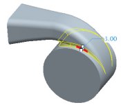
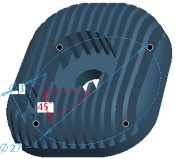
Radial Holes The Hole Tool is used to create all hole types. The type of geometry selected determines which type of hole will be created. In this task, a cylindrical surface is selected as the Primary Reference. There are two Secondary References, used to specify the offset plane and the angle plane. |
| Task 2-3. Create a radial hole on the end of the model for lubrication purposes. |
- Start the Hole Tool from the feature toolbar.
- Select the cylindrical surface shown.
- Right-click and select Secondary References.
- Press CTRL and select datum plane TOP from the model tree and the `D-shaped' surface shown.
- Click To Next
 from the depth options flyout in the dashboard.
- Type 2 as the diameter value in the dashboard, and press ENTER.
- Double-click the angle dimension and enter 45.
- Select the Placement tab in the dashboard, and enter 3 for the Axial offset.
- Click Complete Feature from the dashboard.
|
Creating a Radial Hole |


|
|
The dynamic preview (yellow shading) is the same for Through All and To Next. You can click Preview Feature |
|
|
Selecting Multiple Round References Selecting multiple edges for a round results in multiple round sets by default. Pressing CTRL and selecting multiple edges results in a single round set. |
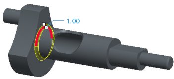
| Task 2-4. Create a round, experimenting with single and multiple round sets. |
- Start the Round Tool
 from the feature toolbar.
- Select the left edge shown in the following figure, and drag the radius handle to 1.
- Select the right edge, and drag its radius handle to 2.
- Notice the second round set is independent from the first.
  Two Round Sets Created |
- Select the Sets tab in the dashboard. Notice there are two sets created.
- Right-click on Set 2 and select Delete. Press CTRL and then select the right edge again.
- Notice how now there are now two references for Set 1 in the Sets tab.
- Drag the radius handle on the model to 4.
- Notice how both rounded edges are now linked to the same radius value.
- Click Complete Feature from the dashboard.
 Round Created |
|
|
Round-All Options You can use the All Convex and All Concave options to quickly round all the edges in a model. |
| Task 2-5. Create rounds on the entire model. |
- Start the Round Tool from the feature toolbar.
- Select the Sets tab.
- Enable All Convex and All Concave .
- Enter 0.2 as the radius value in the dashboard.
- Click Complete Feature .
 Round Created |
|
|
This functionality requires the Allow_Round_All config.pro option. |
- Click Save from the main toolbar, and click OK. Click File > Close Window .
|
|
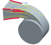
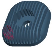
Selecting Intent Edges When selecting edge references, you can often query to Intent Edges. Intent edges allow you to select multiple edges at once, and also are most robust. Instead of referencing specific edges, intent edges reference the underlying feature. |
| Task 2-6. Create an intent edge round on the IMPELLER_HOUSING_2.PRT. |
- Select the Folder Browser , and click Working Directory to view the Part_Modeling folder.
- Select IMPELLER_HOUSING_2.PRT from the browser to view its preview, and then click Open in Pro/E .
- Select IMPELLER_HOUSING_2.PRT from the browser to view its preview, and then click Open in Pro/E
- Select the RIB_FLANGE group from the model tree.
- Right-click and select Resume.
- Select the Insert Indicator
 and drag it before the RIB_FLANGE group.
- Start the Round Tool from the feature toolbar.
- Select the edge shown in the following figure.
- Drag the radius handle to 7.
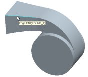 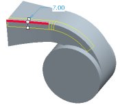 Edge Selected for Round |
- Press CTRL and select the same edge again to de-select it.
- Right-click to query to the intent edge (4 edges) and select it, as shown in the following figure.
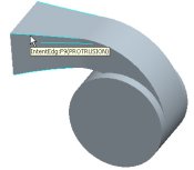  Intent Chain Selected for Round |
|
|
You can also middle-click as a shortcut to Complete Feature |
|
|
Tangent Chain Rounds Tangent chains are automatically selected when selecting edges for a round. |
|
Task 2-7. Create a tangent chain round. |
- Start the Round Tool from the feature toolbar.
- Select the edge shown in the following figure.
- Drag the radius handle to 3.
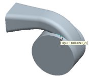  Creating a Tangent Chain Round |
- Click Complete Feature from the dashboard.
|
|
Shell Feature References The shell feature does not require selection of "surfaces to remove", as it can hollow out a model without any references. However, when selecting surfaces to remove, you must press CTRL to select multiple references. |
| Task 2-8. Create a Shell Feature to hollow out the model. |
- Start the Shell Tool
 from the feature toolbar.
- Drag the thickness handle to 2.
- Press CTRL and select the two surfaces shown.
- Click Complete Feature from the dashboard.
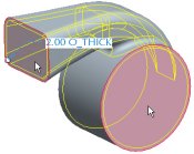  Selecting Surfaces to Remove |
|
|
Rib Feature Depth Options Rib features may use a one side or both sides depth. |
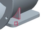
| Task 2-9. Create a Rib from an existing sketch, for strength purposes. |
- Select the Insert Indicator from the model tree.
- Right-click and select Cancel, then click Yes.
- Click Saved View List from the main toolbar and select RIB_VIEW.
- Start the Rib Tool
 from the feature toolbar, and select the RIB_SKETCH.
- Drag either thickness handle to a width of 2.
- Click Complete Feature from the dashboard.
 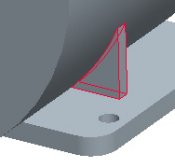
Creating a Rib |
|
|
Mirroring Features The Mirror Tool can mirror solid, surface, and datum features, or groups of features. Mirrored features are dependent on the original by default. |
| Task 2-10. Mirror a rib and a hole to create a symmetric mounting flange. |
- Expand the RIB_FLANGE group in the model tree.
- Press CTRL and select Rib 1 and Hole 2.
- Start the Mirror Tool
 from the feature toolbar.
- Select datum plane FRONT from the model tree.
- Click Complete Feature .
 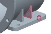 Mirror Created |
- With Mirror 1 still selected, press CTRL and select Rib 1 from the model tree.
- Drag the selected features into the bottom of the RIB_FLANGE group.
- Click Save from the main toolbar, and click OK.
- Click File > Close Window .
|
|
Selecting Multiple Chamfer References Selecting multiple edges for a chamfer results in multiple chamfer sets by default. Pressing CTRL and selecting multiple edges results in a single chamfer set. |
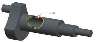
| Task 2-11. Create a chamfer with two sets on the CRANKSHAFT_2.PRT. |
- Select the Folder Browser , and click Working Directory to view the Part_Modeling folder.
- Double-click CRANKSHAFT_2.PRT to open it.
- Start the Chamfer Tool
 from the feature toolbar.
- Select the first edge shown in the following figure and edit the chamfer distance to 0.5 in the dashboard.
- Select the second edge (without using CTRL) and drag the chamfer distance to 1.
|
Chamfer with Two Sets |
-
Select the Sets tab to view the selected references.
-
Click Complete Feature from the dashboard.
 Chamfer Created |
|
|
Chamfer Dimension Schemes Chamfer dimension schemes can be specified using the dashboard, or by right-clicking on the model. |
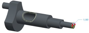
| Task 2-12. Create a chamfer, experimenting with dimensioning options. |
- Start the Chamfer Tool from the feature toolbar.
- Select the edge shown in the following figure.
- Drag the chamfer distance to 1.
 Selecting an Edge |
- Click Saved View List from the main toolbar and select LEFT.
- Zoom in near the chamfer drag handles, and drag the chamfer distance to 2.
- Right-click and select D1 x D2.
- Notice the chamfer dimensioning scheme has updated in the dashboard, and two drag handles are now available.
  Changing Dimension Scheme |
|
|
Flipping Chamfer Direction You can invert the direction of an Angle x D chamfer by using the Flip option. |
| Task 2-13. Experiment with an angular dimensioning scheme for the chamfer. |
- Right-click and select Ang x D.
- Drag the angle handle to 30, then right-click on the handle and select Flip.
- Click Complete Feature .
  Changing Dimension Scheme |
- Click Save from the main toolbar, and click OK.
- Click File > Close Window .
|
|
Creating a Sketch Use the Sketch Tool to create a Sketch feature. The Sketch Tool uses a dialog box instead of the dashboard, so that sketches can still be created when the dashboard is open. |
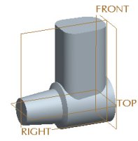
| Task 2-14. Create PISTON_2.PRT, and then create a circular sketch. |
- Click New
 from the main toolbar.
- Enter PISTON_2 as the name, and click OK.
- Click Datum Planes from the main toolbar to enable their display.
- Click Datum Points
 , and Coordinate Systems
  from the main toolbar to disable their display.
- Start the Sketch Tool
 from the feature toolbar.
- Select datum plane TOP from the model.
- Notice that in the Sketch dialog box datum plane RIGHT is automatically selected as the Reference plane, facing the Right.
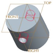
- Click Sketch, and sketch as shown in the following figure:
- Click Close from the References dialog box.
- Click Datum Planes from the main toolbar to disable their display.
- Click Circle
 from the sketcher toolbar, and sketch a circle as shown.
- Middle-click to stop sketching, and to allow items to be selected.
- Double-click on the dimension, type 21, and press ENTER.
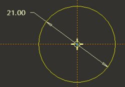 Creating a Sketch |
- Click Complete Sketch
 from the sketcher toolbar.
|
|
Extruding Existing Sketches An existing sketch can be used by the Extrude Tool to create a solid feature. This is often referred to as an External Sketch. The resulting extrude feature is dependent on the selected sketch feature. |
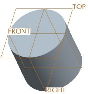
| Task 2-15. Create an Extruded protrusion using the previous sketch. |
- Press CTRL + D to orient to the standard orientation.
- Click Datum Planes from the main toolbar to enable their display.
- With the sketch still selected (highlighted in red), start the Extrude Tool
 from the feature toolbar.
- Drag the depth handle upward to approximately 20.
- Double-click on the depth dimension, and enter 18.5.
- Click on the yellow arrow to flip the direction of feature creation downward.
- Click Complete Feature .
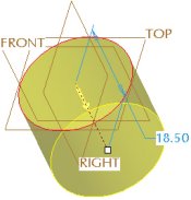  Creating an Extruded Protrusion |
|
|
Creating a group of features The next solid feature to be created is an Extruded Cut to hollow out the PISTON. In order to capture the desired dimensioning scheme for the cut, its sketch will be placed on a datum plane offset from the top surface of the model. We will start the Extrude tool and Pause it. We will then create the datum plane and the sketch. When the Extrude tool is Resumed and completed, the system automatically creates a Group in the model tree. A group allows us to edit and manipulate several features as one. |
| Task 2-16. Start the Extrude tool and then create a datum plane on-the-fly. |
- Start the Extrude Tool from the feature toolbar.
- Click Pause Feature
 from the dashboard.
- Notice the dashboard grays-out, indicating it is paused.
- Start the Datum Plane Tool
 from the feature toolbar.
- Select datum plane TOP from the model.
- Drag the offset handle downwards to 2 as shown in the following figure.
- Select the Properties tab from the Datum Plane dialog box.
- Enter OFFSET as the Name and click OK.
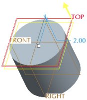 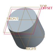 Creating a Datum Plane |
|
|
Sketching Tangent Lines You can easily sketch lines tangent to two entities using the 2-Tangent Line option. |
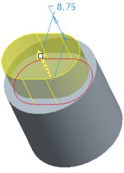
| Task 2-17. Begin an oval sketch on the previous datum plane. |
- With the datum plane still selected, start the Sketch Tool from the feature toolbar.
- Notice that in the Sketch dialog box datum plane RIGHT is automatically selected as the Reference plane, facing the Right.
- Click Sketch and then click Close from the References dialog box.
- Click Datum Planes from the main toolbar to disable their display.
- Click No Hidden
 from the main toolbar.
- Sketch as shown in the following figure
- Right-click and select Centerline, and sketch a vertical centerline.
- Right-click and select Circle and sketch two circles with equal radii as shown.
- Click Constraints
 from the sketcher toolbar.
- Click Symmetric
 , and select the center of each circle and then the centerline.
- Click Close from the Constraints dialog box
- Click 2-Tangent Line
 from the line types flyout in the sketcher toolbar.
- Allowing the cursor to snap to the circles, sketch two lines as shown.
  Creating a Sketch |
|
|
Trimming Entities You can use the Dynamic Trim option to quickly remove unwanted entities. |
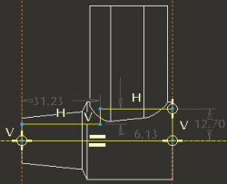
| Task 2-18. Complete the oval sketch by trimming and creating dimensions. |
- Click Dynamic Trim
 from the sketcher toolbar.
- Click and drag to sketch a freehand curve through the inner arcs to remove them.
-
Right-click and select Dimension.
- Select the each arc and middle-click above the sketch to place the horizontal dimension. Select Horiz and click Accept.
- With Dimension
 still depressed, select the two lines and middle-click to the right to place the vertical dimension.
- Middle-click again to allow items to be selected.
- Double-click on the dimension values, and edit as shown.

Completing a Sketch |
- Click Complete Sketch from the sketcher toolbar.
|
|
Completing the Group of Features Now that the datum plane and sketch have been created, we will Resume the complete the Extrude feature, creating an oval cut that hollows out the PISTON. |
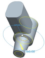
| Task 2-19. Complete the Extruded cut using the previous datum plane and sketch. |
- Click Saved View List from the main toolbar and select Standard Orientation.
- Click Shading
 from the main toolbar.
- Click Resume Feature
 from the dashboard.
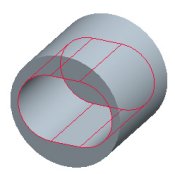
- Complete the extruded cut as shown in the following figure:
- Click on the yellow arrow to flip the direction of feature creation downward.
- Right-click on the depth handle and select Through All.
- Right-click over the model and select Remove Material.
- Click Complete Feature .
 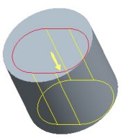 Creating an Extruded Cut |
|
|
Many feature operations can be done by right clicking on drag handles or the model, or from the icons in the dashboard. |
|
|
Automatically Grouped Features The datum plane and sketch have been automatically grouped with the Extrude feature. These features are also automatically Hidden, so they will not clutter up the display. Hidden features are 'grayed-out' in the model tree. |
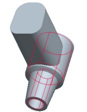
| Task 2-20. Examine the resulting sketches and sketch-based features in the model tree. |
- Orient the model to view the created cut as shown in the following figure.
- Click Show > Expand All from the model tree.
- Notice that Extrude 1 is driven by Sketch 1, and that the original Sketch 1 is automatically hidden in the model tree.
- Notice that Extrude 2 has been automatically grouped with the OFFSET plane and Sketch 2, since the dashboard was paused during their creation. These features are also automatically hidden within the group.
 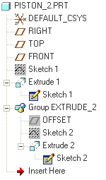 Model and Model Tree |
|
|
Automatically Grouped Features (continued) Creating datum features while a feature dashboard is open allows multiple datum features (of any type) to be auto-grouped with the feature being created. Not only does this allow all the dimensions of the features to be displayed at once, This also allows easy access to unhide or redefine the datum features. Datum features can also be grouped when creating other feature types, such as a datum plane and axis for a coaxial hole. |
| Task 2-21. Continue to examine the resulting sketches and sketch-based features. |
- Click Settings > Tree Filters from the model tree.
- Disable Used Sketch and click Apply.
- Notice the 'used' sketches are removed from the model tree display, but you can still access them by expanding feature nodes.
- Enable Used Sketch and click OK.
 Disabling Used Sketch Display |
|
|
Redefining Sketches and Features A Sketch can be easily selected and edited / redefined by selecting the link to the sketch within the sub-node of the feature, or by selecting the original (hidden) sketch. |
|
|
Linear Holes The Hole Tool is used to create all hole types. The type of geometry selected determines which type of hole will be created. In this case, a datum plane is selected as the Primary Reference. There are two Secondary References, used to specify the linear dimension references. |
| Task 2-22. Create a linear hole to allow for assembly of the PISTON_PIN. |
- Select on the background, and then press CTRL + D to orient to the standard orientation.
- Click Datum Planes from the main toolbar to enable their display.
- Start the Hole Tool from the feature toolbar, and select datum plane FRONT. Right-click and select Secondary References. Press CTRL and select datum planes TOP and RIGHT from the model.
- Continue the hole as shown in the following figure:
- Click Saved View List from the main toolbar and select FRONT.
- Drag the location handle to position the hole approximately as shown on the left.
- Select the Placement tab in the dashboard, and modify the offset value
from datum plane TOP to 8. - Change the dimension type for datum plane RIGHT from Offset to Align.
  Positioning the Hole |
|
|
Hole Depth Options Additional depth options can be found in the appropriate dashboard tab. For holes, select the Shape tab to configure the Side 1 and Side 2 depths. |
| Task 2-23. Complete the hole feature, and select a color appearance for the model. |
- Complete the hole as shown in the following figure:
- Select on the background, and then press CTRL + D to orient to the standard orientation.
- Click the Shape tab in the dashboard.
- Change the existing depth option from Blind to Through All.
- Change the depth option for Side 2 from None to Through All.
- Enter a diameter of 5 in the dashboard, and click Complete Feature .
  Hole Created |
|
|
You can also middle-click as a shortcut to Complete Feature |
- Click View > Color and Appearance from the main menu.
- Select the Blue_Dark appearance and click Apply.
- Click Close from the Appearance Editor dialog box.
- Click Save from the main toolbar, and click OK.
- Click File > Close Window .
|
|
Revolve Tool The revolve tool uses a sketch and a reference for the Axis of Revolution. By default, the system will use the first centerline created in the sketch. If you have multiple centerlines, you can right-click and specify one as an Axis of Revolution. The revolve tool also allows to select an axis or edge as an Axis of Revolution, but it must lie in the sketching plane to be valid. |
| Task 2-24. Create a revolved protrusion in the ENGINE_BLOCK_2.PRT. |
- Click Open
 from the main toolbar, select ENGINE_BLOCK_2.PRT, and click Open.
- Click Datum Axes to enable their display.
- Start the Revolve Tool
 from the feature toolbar, and select the sketch.
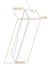 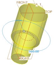 Creating a Revolve |
- Select the Placement tab and notice the current Axis of Revolution is the Internal Centerline.
- Select axis A_1 from the model, then click Preview Feature
 .
.
- Select axis A_1 from the model, then click Preview Feature
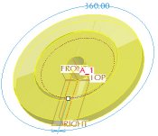  Different Axis of Revolution Selected |
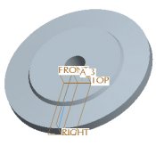
-
Click Resume Feature from the dashboard.
- Select the Placement tab and notice the current Axis of Revolution is A_1.
- Click Internal CL, then drag the angle handle to 270�.
- Click Undo , and click Complete Feature .
- Click Datum Axes from the main toolbar to disable their display.
|
|
Selecting Existing Sketches Selecting an existing sketch is a quick way to create a feature. |
| Task 2-25. Create an Extruded Protrusion from an existing sketch. |
- Start the Extrude Tool from the feature toolbar.
- Select the CYL_SKETCH from the model tree.
- Drag the depth handle to 54 and click Complete Feature .
 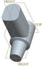 Creating an Extruded Protrusion |
|
|
Automatic Reference Plane Selection By default, the system will select an appropriate reference plane and direction based on the current model orientation. Orienting your model into approximate position before selecting a sketching plane will quickly capture design intent by allowing the system to automatically configure the reference plane and direction. |
| Task 2-26. Create a Revolved Cut, experimenting with the reference plane. |
- Select on the background, and then press CTRL + D to orient to the standard orientation.
- Start the Sketch Tool from the feature toolbar, and select datum plane RIGHT from the model.
- Notice that datum plane TOP is automatically selected as the Reference plane, facing the Left.
- Click Cancel > Yes.
- Orient the model approximately as shown in the following figure.
 Orienting the Model |
- Start the Sketch Tool from the feature toolbar, and select datum plane RIGHT from the model.
- Notice that datum plane TOP is again selected as the Reference plane, but now faces the Top.
- Click Sketch from the Sketch dialog box.
- Sketch as shown in the following figure:
- Click Datum Planes from the main toolbar to disable their display.
- Click No Hidden from the main toolbar.
- Select the left vertical surface as an additional reference.
- Click Close from the References dialog box.
- Right-click and select Centerline. Sketch horizontal centerline.
- Right-click and select Line. Sketch 6 lines approximately as shown, ignoring the dimension values.
- Click Datum Planes
 Creating a Sketch |
- Click Complete Sketch from the sketcher toolbar.
|
|
Revolving a Closed Section By default, selecting a closed section for a revolved cut will result in the material removal side to be the inside of the sketch. This can easily be flipped in the dashboard. |
| Task 2-27. Create a Revolved Cut, hollowing out the crankcase. |
- Click Saved View List from the main toolbar and select Standard Orientation.
- Click Shading from the main toolbar.
- With the sketch still selected, start the Revolve Tool from the feature toolbar.
- Right-click and select Remove Material.
- Click Complete Feature .
  Revolved Cut Created |
- Click Save from the main toolbar, and click OK. Click File > Close Window .
- Click File > Erase > Not Displayed and click OK.
|
|
Copying Features Features copied using Copy and Paste are independent of the original. initially, the copied features use the same dimensions and options (depth, etc) as the original, but can be modified. |
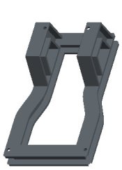
| Task 2-28. Copy a hole feature in the FRAME_2.PRT. |
- Select the Folder Browser , and click Working Directory . Select FRAME_2.PRT from the browser to view its preview, and then click Open in Pro/E .
- Click Saved View List from the main toolbar and select HOLE.
- Select the hole (Hole 3) and click Copy
 from the main toolbar.
- Select the body of the model, and then select the placement surface as shown.
- Click Paste
 , and drag the copied hole upward on the model,
- Edit the dimensions of the copied hole as shown.
- Click Complete Feature .
   Hole Copied |
|
|
You can also press CTRL+C and CTRL+V for Copy and Paste. |
|
|
Mirroring All Features You can mirror all features in the model by selecting the part node from the mode tree as input for the Mirror Tool. |
| Task 2-29. Mirror all features in the model, creating a symmetric part. |
-
Select on the background to de-select the hole.
-
Press CTRL + D to orient to the standard orientation.
- Select the FRAME_2.PRT node from the model tree.
- Start the Mirror Tool from the feature toolbar.
- Select datum plane RIGHT from the model tree.
- Click Complete Feature .
  Mirror Created |
- Click Save from the main toolbar, and click OK.
- Click File > Close Window .
|
|
Linear Dimension Patterns The Pattern Tool is used to create all pattern types. You can create a pattern of a feature or group by using the Dimension option, and selecting a linear dimension to increment. |
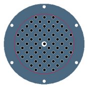
| Task 2-30. Create a linear dimension pattern on the ENGINE_HEAD_2.PRT. |
- Click Open from the main toolbar, select ENGINE_HEAD_2.PRT, and click Open.
- Select the FIN_CUT from the model tree, and start the Pattern Tool
 from the feature toolbar.
- Select the 13 dimension, and enter -2 as the increment.
- Select the Dimensions tab to view the increment value.
- Enter 14 as the number of members in the dashboard.
- Click Complete Feature .
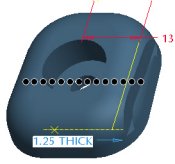  Pattern Created |
|
|
You can click on any of the preview 'dots' to disable that member of the pattern. |
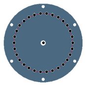
- Select the THRU_HOLE from the model tree, then press CTRL and select the C-BORE.
- Right-click and select Resume, then press CTRL and de-select the C-BORE.
  THRU_HOLE and C-BORE Resumed |
|
|
Rotational Dimension Patterns The Pattern Tool is used to create all pattern types. You can create a pattern of a feature or group by using the Dimension option, and selecting an angular dimension to increment. |
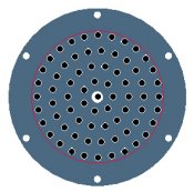
| Task 2-31. Create a rotational dimension pattern of the THRU_HOLE. |
- With the THRU_HOLE still selected, start the Pattern Tool from the feature toolbar.
- Select the 45 dimension, and enter 90 as the increment.
- Enter 4 as the number of members in the dashboard.
- Click Complete Feature .
  THRU_HOLE Patterned |
- Select the C-BORE, right-click and select Pattern.
- Notice that Reference is selected as the type.
- Click Complete Feature .
  C-BORE Reference Patterned |
|
|
Instead of creating a reference pattern, you can also quickly group the two hole features and pattern the group. |
-
Click Save from the main toolbar, and click OK.
-
Click File > Close Window.
|
|
Rotational Dimension Patterns (continued) When creating a rotational dimension pattern of a sketch-based feature, it is recommended that the angular dimension belong to a datum plane in the same group. The datum plane can be used for either the sketching plane or the reference plane for the sketch. |
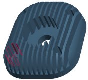
| Task 2-32. Examine and modify the group of features comprising the tab on the ENGINE_COVER_2.PRT. |
- Click Open from the main toolbar, select ENGINE_COVER_2.PRT, and click Open.
- Expand the EXTRUDE_3 group in the model tree and examine the existing features.
- The datum plane (DTM2) and Sketch 3 were created with the Extrude dashboard paused, allowing the features be auto-grouped with Extrude 3.
- DTM2 was utilized as the reference plane for the sketch at a 45� angle.
  Completed Feature |
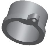
- Press CTRL and select A_15 and Hole 2, then drag the two features into the bottom of the EXTRUDE_3 group.
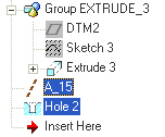 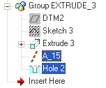 Features Placed in Group |
|
|
Patterning a Group When creating a Dimension Pattern of a Group of features, dimension values from any feature in the group are available for selection. |
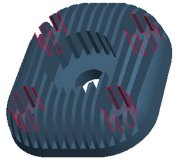
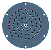
| Task 2-33. Create a rotational dimension pattern of the EXTRUDE_3 group. |
- Select the EXTRUDE_3 group, then start the Pattern Tool from the feature toolbar.
- Notice all dimensions from features in the group appear.
- Select the 45 dimension, and enter 90 as the increment.
- Enter 4 as the number of members in the dashboard.
- Click Complete Feature .
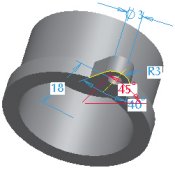 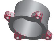 Pattern Created |
- Click Save from the main toolbar, and click OK.
- Click File > Close Window .
|
|
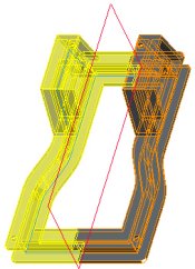
Snapping to References When dragging a depth or reference handle, you can 'snap' to references by pressing the SHIFT key. |
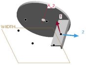
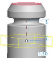
| Task 2-34. Create an extrude feature on the IMPELLER_2.PRT that will be used to create a pattern. |
- Click Open from the main toolbar, select IMPELLER_2.PRT, and click Open.
- Select the BLADE_SKETCH from the model tree, then right-click and select Edit.
- Notice this sketch has no angle dimension to control the orientation of the sketch.
- With the sketch still selected, start the Extrude Tool from the feature toolbar.
- Click Datum Planes to enable their display.
- Press SHIFT and drag the depth handle to snap to datum plane WIDTH.
- Click Solid
 and Thicken Sketch
  . Enter 1.5 for the thickness value.
- Click Change Material Direction
 twice to thicken towards the inside of the sketch.
- Click Datum Planes
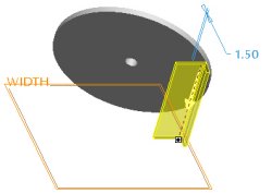 Creating a Thin Protrusion |
- Click Complete Feature .
|
|
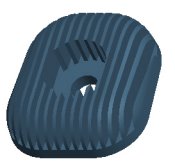
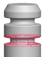
Creating Axis Patterns The Axis pattern option can be used to rotationally pattern a feature or group about a selected axis, regardless of their dimensioning scheme. The Set Angular Extent option within Axis pattern eliminates the need to write a typical "Angle=360/P1" relation to equally space pattern members. |
| Task 2-35. Create pattern of equally spaced blades. |
- With the Extrude 2 feature still selected, right-click and select Pattern.
- Click Datum Axes to enable their display.
- Change the pattern type from Dimension to Axis, and select axis A_2.
- Drag the pattern spacing handle to 45 to view the effect on the pattern preview dots.
- Enter 6 as the number of members in the dashboard.
- Click Set Angular Extent
 in the dashboard.
- Click Complete Feature .
- Click Datum Axes
 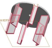 Pattern Created |
- Click Save from the main toolbar, and click OK.
- Click File > Close Window .
|
|
Creating Direction Patterns The Direction pattern option can be used to linearly pattern a feature or group in one or two directions, regardless of their dimensioning scheme. |
| Task 2-36. Create a linear direction pattern of cooling fins on the ENGINE_BLOCK_3.PRT. |
- Select the Folder Browser , and click Working Directory to view the Part_Modeling folder.
- Double-click ENGINE_BLOCK_3.PRT to open it.
- Press CTRL and select FIN_DTM, FIN_SKETCH, and FIN_EXTRUDE from the model tree.
- Right-click and select Group.
- Right-click and select Rename. Enter FIN as the name.
|
|
Manually created groups are equivalent to automatically created groups. |
- Create a pattern as shown in the following figure:
- With the FIN group still selected, right-click and select Pattern.
- Change the pattern type from Dimension to Direction.
- Select the top surface of the model.
- Click Flip First Direction
 from the dashboard.
- Enter 14 as the number of members and drag the pattern spacing handle to 2.
- Click Complete Feature .
  Direction Pattern Created |
|
|
Reordering Features You can quickly drag and drop features to reorder them in the model tree. |
| Task 2-37. Reorder the BORE hole to be after the pattern, to properly remove material. |
- Select the BORE feature in the model tree.
- Drag to reorder it after Pattern 1.
  BORE Reordered |
|
|
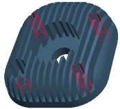
Copying features by Rotating You can use Copy and Paste Special to copy and rotate features or a group. The Paste Special dialog box has options for Dependency, Move/Rotate, and Advanced Reference Configuration. |
| Task 2-38. Copy and rotate a group of features, creating a second structural rib. |
- Click Saved View List from the main toolbar and select FRONT.
- Create a copy as shown in the following figure:
- Select the RIB group and click Copy from the main toolbar.
- Click Paste Special
 from the main toolbar.
- Select both Make Copies Dependent and Apply Move/Rotate Transformations. Click OK.
- Click Rotate
 from the dashboard, and select axis A_2.
- Drag the angle handle upward and then enter -20 for the angle.
- Click Complete Feature
- Select the RIB group and click Copy
|
Copy Created |
- Click Save from the main toolbar, and click OK.
- Click File > Close Window .
|
|
Copying features by Translating You can use Copy and Paste Special to copy and translate features or a group. The Paste Special dialog box has options for Dependency, Move/Rotate, and Advanced Reference Configuration. |
| Task 2-39. Copy and translate features on the GLOW_PLUG_2.PRT. |
- Select the Folder Browser , and click Working Directory .
- Double-click GLOW_PLUG_2.PRT to open it.
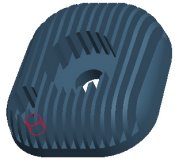
- Create a round as shown in the following figure:
- Start the Round Tool from the feature toolbar.
- Zoom in, then press CTRL and select the two edges shown (ignore the radius value).
- Right-click and select Full Round, then click Complete Feature .
- Start the Round Tool
  Creating a Full Round |
- With the last round still selected, press CTRL and select Round 1 and Revolve 2 from the model tree.
- Right-click and select Group.
- Create a copy as shown in the following figure:
- With the group still selected, click Copy from the main toolbar.
- Click Paste Special from the main toolbar.
- Select both Make Copies Dependent and Apply Move/Rotate Transformations. Click OK.
- Click Translate
 from the dashboard and select the top model surface.
- Enter -1.5 for the translate value and click Complete Feature .
- With the group still selected, click Copy
  Creating a Copy |
- Click Save from the main toolbar, and click OK.
- Click File > Close Window .
|
|
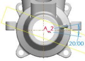
Creating Fill Patterns A Fill Pattern allows you to pattern a feature by 'filling' the area within a selected Sketch with multiple pattern members. There are several options for the fill pattern type, and various spacing options. The sketch selected for the Fill pattern can be any shape, and if redefined the pattern will update accordingly - members will be added/removed as necessary. |
| Task 2-40. Create a fill pattern on the FLANGE_2.PRT. |
- Click Open from the main toolbar, select FLANGE_2.PRT, and click Open.
- Click Datum Axes to disable their display.
- Click Saved View List from the main toolbar and select FRONT.
- Select the CTR_HOLE feature from the model tree, and click Edit > Pattern.
- Notice the pattern type is set to Fill
- Select the circular sketch feature from the model.
- Edit the pattern spacing
 to 6 in the dashboard. (Do not complete the pattern yet).
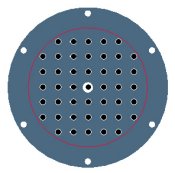  Creating a Fill Pattern |
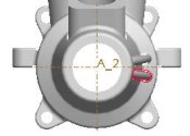
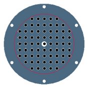
- Edit the pattern as shown in the following figure:
- Select Triangle as the pattern spacing type in the dashboard.
- Select Circle as the pattern spacing type and edit the radial spacing
 to 7.
to 7.
  Editing a Fill Pattern |
|
|
Creating Fill Patterns (continued) You can click on any of the preview 'dots' to disable that member of the pattern. |
| Task 2-41. Complete the Fill Pattern. |
- Edit the pattern as shown in the following figure:
- Select Curve as the pattern spacing type in the dashboard.
- Select Spiral as the pattern spacing type in the dashboard.
- Edit the grid rotation
 to 180 degrees.
  Editing a Fill Pattern |
- Edit the pattern as shown in the following figure:
- Select the 5 pattern members shown on the left (white dots) to disable them.
- Click Complete Feature .
  Fill Pattern Completed |
- Click Save from the main toolbar, and click OK.
- Click File > Close Window .
- Click File > Erase > Not Displayed and click OK to erase all models from memory.
This completes the second exercise.
CONGRATULATIONS!
You have completed the part modeling portion of the Advanced Hands-On Workshop tutorial.
If you wish, please continue with 2 challenge exercises to further experiment with Pro/ENGINEER Wildfire 2.0 enhancements:
- Creating Assemblies (6 pages)
- Creating Drawings (8 pages)
SUMMARY
Now that you have completed this section of the tutorial, you should be able to:
- Preview and Open Models.
- Use new orientation tools to spin, pan, and zoom
- Select components and features using various techniques.
- Hide / Unhide components and features.
- Delete and edit features.
- Redefine features using the dashboard.
- Create datum axes and planes.
- Create holes, rounds, chamfers, and shells.
- Created extrude, revolve, and rib features.
- Copy, mirror, and pattern features.
| Exercise 3: Creating Assemblies. |
Objectives
After successfully completing this exercise, you will know how to:
- Drag assembled components using Drag Component.
- Drag components during assembly using CTRL + ALT + Left Mouse Button.
- Convert constraints into connections.
- Setup and utilize component interfaces.
|
|
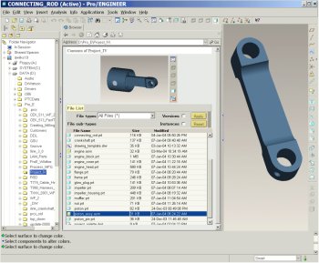
Dragging Assembled Components The Drag Component option allows you to kinematically drag components as a mechanism. Drag Component is valid for mechanism connections or any under-constrained (packaged) components. |
| Task 3-1. Drag the CONNECTING_ROD on the PISTON_ASSY.ASM, and convert its constraints into connections. |
- In the Folder Browser , locate the Asm_Drw folder.
- Click on the Asm_Drw folder to view the contents of the folder in the browser.
- Right-click on the Asm_Drw folder and select Set Working Directory.
- Select the PISTON_ASSY.ASM from the browser, and then click Open in Pro/E .
- Click Drag Component
 from the main toolbar.
 - Click and release to move the connecting rod as shown.
- Click to accept the new position.
- Middle-click when finished.
  Dragging the CONNECTING_ROD |
- Select the CONNECTING_ROD.PRT, right-click and select Edit Definition.
- Notice the Insert and Align constraints, and the Partially Constrained status.
- Click Convert Constraints to Connections
 and notice a Pin connection is created.
- Click OK from the component placement dialog box.
- Click File > Close Window .
|
|
Positioning Components You can press CTRL + ALT and use the Right Mouse Button to position a component during assembly. |
| Task 3-2. Assemble the PISTON_ASSY to the ENGINE.ASM with a Cylinder Connection. |
- Select the Folder Browser , and click Working Directory .
- Double-click the ENGINE.ASM to open it.
- Click View > Display Settings > Model Display from the main menu. Select the Shade tab and enable Transparency. Click OK from the Model Display dialog box.
- Select the Folder Browser , and click Working Directory .
- Drag the width of the browser so that the file list and the model are visible.
- Select the PISTON_ASSY.ASM, then drag it into the graphics window to begin assembling it.
- Press CTRL + ALT, then right-click and drag to position the PISTON_ASSY.ASM as shown.
- Select the Connect tab from the Component Placement dialog box.
- Change the Connection Type to from Pin to Cylinder.
- Select the cylindrical surfaces as shown.
 Selecting Surfaces |
|
|
Dragging Components During Assembly You can press CTRL + ALT and use the Left Mouse Button to kinematically drag components during assembly. |
| Task 3-3. Create a second cylinder connection on the end of the CONNECTING_ROD. |
- Click New Constraint
 from the Component Placement dialog box.
- Middle-drag to spin the entire assembly as shown in the following figures.
- Press CTRL + ALT and use the left mouse button to drag the CRANKSHAFT closer to the CONNECTING_ROD as shown on the left.
- Zoom in and select the cylindrical surfaces as shown on the right.
- Press CTRL + ALT and use the left mouse button to drag the CRANKSHAFT again.
- Notice the PISTON_ASSY now moves accordingly.
  Selecting Surfaces |
- Click OK from the Component Placement dialog box.
- Press CTRL + D to orient to the Standard Orientation.
- Click Drag Component from the main toolbar.
- Select a point on the CRANKSHAFT.PRT and move the mouse to drag the mechanism.
- Middle-click when finished.
|
|
The mechanism could be run by clicking Run Analysis |
- Click View > Display Settings > Model Display from the main menu.
- Select the Shade tab and disable Transparency.
- Click OK from the Model Display dialog box.
|
|
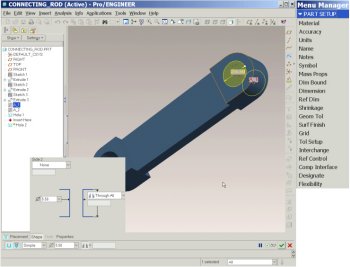
Component Interfaces You can setup and use Component Interfaces to rapidly assemble commonly used components. You can specify assembly references on the component, which will be selected automatically when assembling the component. |
| Task 3-4. Setup a Component Interface on the BOLT.PRT. |
- Select the Folder Browser , and click Working Directory .
|
|
IMPORTANT- In the next step, you will be opening a second Pro/ENGINEER window. You must resize and reposition the window to the right of the tutorial. |
- Double-click BOLT.PRT, select The Generic, and click Open.
- Click Edit > Setup from the main menu.
- Click Comp Interface from the menu manager.
- Change the constraint type from Mate to Insert, and select the cylindrical surface shown.
- Click Add, and then select the planar surface shown.
  Selecting Insert and Mate Surfaces. |
- Click OK from the Component Interface dialog box.
- Click Window > Close to return to ENGINE.ASM.
- Select on the textured area to the right of the browser to collapse it.
- Select the ENGINE_HEAD.PRT from the model tree, then press SHIFT and select the ENGINE_COVER.PRT.
- Right-click and select Resume.
|
|
Component Interfaces (continued) When assembling a component, you can use Component Interfaces manually or automatically. When used manually, only the assemble references must be selected. When used automatically, only an approximate location must be selected for the component. |
| Task 3-5. Assemble the BOLT.PRT manually and automatically using the Component Interface. |
- Click Add Component
 from the feature toolbar.
- Select the BOLT.PRT and click Open.
- Select the BOLT_5 instance, and click Open.
- Select the INTFC001 interface, and click OK.
- Select insert and mating surfaces as shown in the following figure.
- Click OK from the Component Placement dialog box.
   Selecting Insert and Mating surfaces. |
- Click Add Component from the feature toolbar.
- Accept the BOLT_5 instance, and click Open.
- Select the INTFC001 interface, and click AutoPlace.
- Select a location in the bolt hole on the opposite side and click OK.
 Second BOLT Assembled. |
|
|
Component Interfaces (continued) When assembling a component, you can also use Component Interfaces automatically by dragging and dropping from the browser. |
| Task 3-6. Drag and drop to assemble the BOLT.PRT using the Component Interface. Then create a Reference pattern. |
-
Select the Folder Navigator and click Working Directory .
- Drag the size of the browser so both the model and browser are visible.
- Re-orient the model, then select BOLT.PRT and drag it directly into the hole.
- Select the BOLT_8.PRT instance and click Open.
- Select the bolt, right-click and select Pattern.
- Click Complete Feature from the dashboard.
  Drag and Drop BOLT.PRT |
-
Click Save from the main toolbar and click OK.
-
Click Window > Close.
This completes the third exercise.
| Exercise 4: Creating Drawings (CHALLENGE). |
Objectives
After successfully completing this exercise, you will know how to:
- Use the Drawing View dialog box.
- Undo and Redo actions in drawings.
- Use the Pause Show and Erase option.
|
|
Saving View Orientations You can use the View Manager dialog box to create and edit saved view orientations. The view manager is also used to create Simplified Reps, Style Reps, Explode States, and Cross Sections. |
| Task 4-1. Create a saved orientation on the ENGINE_BLOCK.prt using the View Manager. |
- Click Open from the main toolbar, select ENGINE_BLOCK.PRT, and click Open.
- Orient the model as shown in the following figure.
 Model Reoriented |
- Start the View Manager
 from the main toolbar.
- Select the Orient tab then click New.
- Type 3D as the name and press ENTER.
- Click Close from the View Manager dialog box.
- Click Saved View List from the main toolbar.
- Notice 3D is available and select Standard Orientation.
-
Click Window > Close.
|
|
Creating Drawing Views Automatically You can setup and use a Drawing Template to specify a default view configuration when creating a new drawing. The template can also contain customized drawing format. |
| Task 4-2. Create a new drawing of the ENGINE_BLOCK.PRT. |
- Click New and select Drawing as the Type.
- Type ENGINE_COMPONENTS as the Name and press ENTER.
- Notice that the ENGINE_BLOCK.PRT is used as the Default Model, and that drawing_template is the current template.
- Click OK from the New Drawing dialog box.
- Enter parameter information to create the drawing:
- Type YOUR NAME at the prompt and press ENTER.
- The new drawing is created, which uses the template to place 3 isometric views and a title block.
- Double-click the date cell in the title block to the right of your name and enter &todays_date.
- Click OK from the Note Properties dialog box.
-
Drag the width of the model tree to the left to collapse it.
 Showing drawing with three views created. |
- Double-click on the SCALE value in the bottom left corner, and enter 1.75 for the scale.
|
|
Creating Projection Views You can quickly create projection views by selecting a parent view and using the Insert Projection View option. A yellow preview outline of the view is displayed to aid in placement. |
| Task 4-3. Create a projection view. |
- Select the FRONT view.
- Right-click and select Insert Projection View.
- Select a location to the left of the front view as shown in the following figure.
 Showing location of projected view. |
|
|
Creating General Views You can use the Insert General View option to place a general view using the Drawing View dialog box, which contains all settings and options used when creating views. |
| Task 4-4. Create additional projection and general views. |
- Select on the drawing background to de-select the current view.
- Right-click and select Insert General View. Select a location in the upper right corner of the sheet.
- Select 3D from the model view name list and click Apply.
- Select the Scale category from the Drawing View dialog box.
- Click Custom Scale, enter 1.5, and click Apply.
- Click Close from the Drawing View dialog box.
- Right-click and select Lock View Movement to disable it.
- Select views and drag them to new positions, as shown in the following figure.
 Showing position of views. |
- Click Undo to move the last view to its previous position. Click Redo .
|
|
Creating a Cross-Section View The Drawing View dialog box can be used to display an existing cross section. |
| Task 4-5. Configure the RIGHT view to have a cross section. |
- Select the RIGHT view, right-click and select Properties.
- Select the Sections category from the Drawing View dialog box.
- Click 2D cross-section, and click Add Section
 .
.
- Select A from the drop-down list of section names, and then click OK.
- With the view still selected, right-click and select Add Arrows, then select the FRONT view.
- Select and drag the arrows as necessary.
 Figure 82: Cross Section Created |
|
|
Creating a Detail View When creating a Detail view, you select a location on an existing view, sketch a spline around the chosen location, and then place the view on the sheet. The scale and name of the view can be adjusted after placement. |
| Task 4-6. Create a detail view, showing an enlarged view of the cooling fins. |
- Select on the background to de-select any items.
- Click Insert > Drawing View > Detailed from the main menu.
- Zoom in and select the location shown as the center point on the RIGHT view.
- Select locations to sketch a spline as shown. Middle-click to complete the spline.
  Showing detailed view center point. |
- Click Refit
 from the main toolbar.
- Select a location for the detailed view in the upper left corner of the sheet.
- Configure the view as shown in the in the following figure:
- Zoom in to the detail view.
- Select the SCALE note beneath the view, double-click the 3.500 value and enter 7.5.
- Select and drag the view to reposition it if necessary.
- Select the cross-hatching in the detail view, right-click and select Properties.
- Click Det Indep > Spacing > Half > Half > Done from the menu manager.
  Detail View Updated |
|
|
Pausing Show and Erase You can use the Pause Show and Erase and Resume Show and Erase options to move and manipulate dimensions without leaving the Show and Erase dialog box. |
| Task 4-7. Show dimensions for one of the cooling fins in the detail view. |
- Click Show/Erase
 from the drawing toolbar.
- Click Show from the Show/Erase dialog box, then click Dimensions
 .
.
- Click Feature and View, and select Extrude_4 in the detail view as shown.
- Right-click and select Pause Show and Erase.
- Select and drag the dimensions as shown on the right.
  Selecting a Feature |
|
|
You can also show all dimensions for a selected view by right-clicking and selecting Show Dimensions. |
-
Right-click and select Resume Show and Erase.
-
Click Accept All > Close in the Show/Erase dialog box.
-
Select the 2 dimension, right-click and select Flip Arrows.
-
Select the dimension and move the text between the dimension lines.
|
|
Many options for views, dimensions, notes, tables, and the drawing itself are available in the right-click shortcut menu. |
|
|
Cleaning Up Dimensions You can use the Cleanup Dimensions dialog box to evenly space and increment dimensions from the view outline or selected geometry. |
| Task 4-8. Cleanup the dimensions in the detail view. |
-
Select the detail view, right-click and select Cleanup Dimensions.
- Disable the Create Snap Lines check box.
- Select the Cosmetic tab, disable Center Text, and click Apply.
- The dimensions should appear as shown in the following figure.
 Cleaned Dimensions |
-
Select the Placement tab and click Baseline.
- Select the edge shown below in red.
- Click Apply > Close.

Cleaning Dimensions |
- The dimensions should appear as shown in the following figure on the left.
- Select each dimensions and move approximately as shown on the right.
  Moving Dimensions. |
- Click Undo twice to return the dimensions to their previous 'cleaned' locations.
- Click Save from the main toolbar, and click OK.
This completes the fourth exercise.
CONGRATULATIONS !
You have completed the Advanced Hands-On Workshop tutorial.
SUMMARY
Now that you have completed the tutorial, you should be able to:
- Describe Pro/ENGINEER Wildfire 2.0 concepts and interface.
- Modeling Basics
- Preview and Open Models.
- Use new orientation tools to spin, pan, and zoom
- Select components and features using various techniques.
- Hide / Unhide components and features.
- Delete and edit features.
- Redefine features using the dashboard.
- Creating Part Models
- Create datum axes and planes.
- Create holes, rounds, chamfers, and shells.
- Created extrude, revolve, and rib features.
- Copy, mirror, and pattern features.
- Creating Assemblies
- Drag assembled components using Drag Component.
- Drag components during assembly using CTRL + ALT + Left Mouse Button.
- Convert constraints into connections.
- Setup and utilize component interfaces.
- Creating Drawings
- Use the Drawing View dialog box.
- Undo and Redo actions in drawings.
- Use the Pause Show and Erase option.
Want to take best-in-class Pro/ENGINEER training without the inconvenience and expense of travel?

It easy � just join PTC University! PTC University is an online portal that combines the depth and breadth of PTC�s traditional training programs with the convenience, flexibility, and affordability of distance learning.
With PTC University, you have access to the most effective forms of distance learning including Virtual Classes, Web-based Training, e-Knowledge Assets, and Communities of Practice.
Whether you want to polish your existing skills or learn a new technique, PTC University will give you the right information, at the right time, with right media - without ever having to leave the comfort of your desk.
Learn more on how PTC University can help you improve your product development practices at http://www.ptc.com/go/learning.
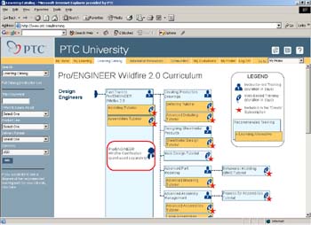
Copyright � 2004 Parametric Technology Corporation. All Rights Reserved.
User and training documentation from Parametric Technology Corporation (PTC) is subject to the copyright laws of the United States and other countries and is provided under a license agreement that restricts copying, disclosure, and use of such documentation. PTC hereby grants to the licensed user the right to make copies in printed form of this documentation if provided on software media, but only for internal/personal use and in accordance with the license agreement under which the applicable software is licensed. Any copy made shall include the PTC copyright notice and any other proprietary notice provided by PTC. This documentation may not be disclosed, transferred, modified, or reduced to any form, including electronic media, or transmitted or made publicly available by any means without the prior written consent of PTC and no authorization is granted to make copies for such purposes.
Information described herein is furnished for general information only, is subject to change without notice, and should not be construed as a warranty or commitment by PTC. PTC assumes no responsibility or liability for any errors or inaccuracies that may appear in this document.
The software described in this document is provided under written license agreement, contains valuable trade secrets and proprietary information, and is protected by the copyright laws of the United States and other countries. It may not be copied or distributed in any form or medium, disclosed to third parties, or used in any manner not provided for in the software licenses agreement except with written prior approval from PTC. UNAUTHORIZED USE OF SOFTWARE OR ITS DOCUMENTATION CAN RESULT IN CIVIL DAMAGES AND CRIMINAL PROSECUTION.
Parametric Technology Corporation, 140 Kendrick Street, Needham, MA 02494 USA
Registered Trademarks of Parametric Technology Corporation or a Subsidiary
Advanced Surface Design, Behavioral Modeling, CADDS, Computervision, CounterPart, EPD, EPD.Connect, Expert Machinist, Flexible Engineering, GRANITE, HARNESSDESIGN, Info*Engine, InPart, MECHANICA, Optegra, Parametric Technology, Parametric Technology Corporation, PartSpeak, PHOTORENDER, Pro/DESKTOP, Pro/E, Pro/ENGINEER, Pro/HELP, Pro/INTRALINK, Pro/MECHANICA, Pro/TOOLKIT, Product First, PTC, the PTC logo, PT/Products, Shaping Innovation, and Windchill.
Trademarks of Parametric Technology Corporation or a Subsidiary
3DPAINT, Associative Topology Bus, AutobuildZ, CDRS, Create Collaborate Control, CV, CVact, CVaec, CVdesign, CV-DORS, CVMAC, CVNC, CVToolmaker, DataDoctor, DesignSuite, DIMENSION III, DIVISION, e/ENGINEER, eNC Explorer, Expert MoldBase, Expert Toolmaker, ISSM, KDiP, Knowledge Discipline in Practice, Knowledge System Driver, ModelCHECK, MoldShop, NC Builder, Pro/ANIMATE, Pro/ASSEMBLY, Pro/CABLING, Pro/CASTING, Pro/CDT, Pro/CMM, Pro/COLLABORATE, Pro/COMPOSITE, Pro/CONCEPT, Pro/CONVERT, Pro/DATA for PDGS, Pro/DESIGNER, Pro/DETAIL, Pro/DIAGRAM, Pro/DIEFACE, Pro/DRAW, Pro/ECAD, Pro/ENGINE, Pro/FEATURE, Pro/FEM-POST, Pro/FICIENCY, Pro/FLY-THROUGH, Pro/HARNESS, Pro/INTERFACE, Pro/LANGUAGE, Pro/LEGACY, Pro/LIBRARYACCESS, Pro/MESH, Pro/Model.View, Pro/MOLDESIGN, Pro/NC-ADVANCED, Pro/NC-CHECK, Pro/NCMILL, Pro/NCPOST, Pro/NC-SHEETMETAL, Pro/NC-TURN, Pro/NC-WEDM, Pro/NC-Wire EDM, Pro/NETWORK ANIMATOR, Pro/NOTEBOOK, Pro/PDM, Pro/PHOTORENDER, Pro/PIPING, Pro/PLASTIC ADVISOR, Pro/PLOT, Pro/POWER DESIGN, Pro/PROCESS, Pro/REPORT, Pro/REVIEW, Pro/SCAN-TOOLS, Pro/SHEETMETAL, Pro/SURFACE, Pro/VERIFY, Pro/Web.Link, Pro/Web.Publish, Pro/WELDING, Product Development Means Business, ProductView, PTC Precision, Shrinkwrap, Simple Powerful Connected, The Product Development Company, The Way to Product First, Wildfire, Windchill DynamicDesignLink, Windchill PartsLink, Windchill PDMLink, Windchill ProjectLink, and Windchill SupplyLink.
Patents of Parametric Technology Corporation or a Subsidiary
Additional foreign equivalents may be issued or pending � contact PTC for further information:
Registration No. Issue Date
6,665,569 B1 16-December-2003
6,625,607 B1 23-September-2003
6,580,428 B1 17-June-2003
GB2354684B 02-July-2003
GB2384125 15-October-2003
GB2354096 12-November-2003
6,608,623 B1 19 August 2003
GB2353376 05-November-2003
GB2354686 15-October-2003
6,545,671 B1 08-April-2003
GB2354685B 18-June-2003
6,608,623 B1 19 August-2003
6,473,673 B1 29-October-2002
GB2354683B 04-June-2003
6,447,223 B1 10-Sept-2002
6,308,144 23-October-2001
5,680,523 21-October-1997
5,838,331 17-November-1998
4,956,771 11-September-1990
5,058,000 15-October-1991
5,140,321 18-August-1992
5,423,023 05-June-1990
4,310,615 21-December-1998
4,310,614 30-April-1996
4,310,614 22-April-1999
5,297,053 22-March-1994
5,513,316 30-April-1996
5,689,711 18-November-1997
5,506,950 09-April-1996
5,428,772 27-June-1995
5,850,535 15-December-1998
5,557,176 09-November-1996
5,561,747 01-October-1996
Third-Party Trademarks
Adobe is a registered trademark of Adobe Systems. Advanced ClusterProven, ClusterProven, and the ClusterProven design are trademarks or registered trademarks of International Business Machines Corporation in the United States and other countries and are used under license. IBM Corporation does not warrant and is not responsible for the operation of this software product. AIX is a registered trademark of IBM Corporation. Allegro, Cadence, and Concept are registered trademarks of Cadence Design Systems, Inc. Apple, Mac, Mac OS, and Panther are trademarks or registered trademarks of Apple Computer, Inc. AutoCAD and Autodesk Inventor are registered trademarks of Autodesk, Inc. Baan is a registered trademark of Baan Company. CADAM and CATIA are registered trademarks of Dassault Systemes. COACH is a trademark of CADTRAIN, Inc. DOORS is a registered trademark of Telelogic AB. FLEXlm is a trademark of Macrovision Corporation. Geomagic is a registered trademark of Raindrop Geomagic, Inc. EVERSYNC, GROOVE, GROOVEFEST, GROOVE.NET, GROOVE NETWORKS, iGROOVE, PEERWARE, and the interlocking circles logo are trademarks of Groove Networks, Inc. Helix is a trademark of Microcadam, Inc. HOOPS is a trademark of Tech Soft America, Inc. HP-UX is a registered trademark and Tru64 is a trademark of the Hewlett-Packard Company. I-DEAS, Metaphase, Parasolid, SHERPA, Solid Edge, and Unigraphics are trademarks or registered trademarks of Electronic Data Systems Corporation (EDS). InstallShield is a registered trademark and service mark of InstallShield Software Corporation in the United States and/or other countries. Intel is a registered trademark of Intel Corporation. IRIX is a registered trademark of Silicon Graphics, Inc. LINUX is a registered trademark of Linus Torvalds, MatrixOne is a trademark of MatrixOne, Inc. Mentor Graphics and Board Station are registered trademarks and 3D Design, AMPLE, and Design Manager are trademarks of Mentor Graphics Corporation. MEDUSA and STHENO are trademarks of CAD Schroer GmbH. Microsoft, Microsoft Project, Windows, the Windows logo, Windows NT, Visual Basic, and the Visual Basic logo are registered trademarks of Microsoft Corporation in the United States and/or other countries. Netscape and the Netscape N and Ship's Wheel logos are registered trademarks of Netscape Communications Corporation in the U.S. and other countries. Oracle is a registered trademark of Oracle Corporation. OrbixWeb is a registered trademark of IONA Technologies PLC. PDGS is a registered trademark of Ford Motor Company. RAND is a trademark of RAND Worldwide. Rational Rose is a registered trademark of Rational Software Corporation. RetrievalWare is a registered trademark of Convera Corporation. RosettaNet is a trademark and Partner Interface Process and PIP are registered trademarks of �RosettaNet,� a nonprofit organization. SAP and R/3 are registered trademarks of SAP AG Germany. SolidWorks is a registered trademark of SolidWorks Corporation. All SPARC trademarks are used under license and are trademarks or registered trademarks of SPARC International, Inc. in the United States and in other countries. Products bearing SPARC trademarks are based upon an architecture developed by Sun Microsystems, Inc. Sun, Sun Microsystems, the Sun logo, Solaris, UltraSPARC, Java and all Java based marks, and �The Network is the Computer� are trademarks or registered trademarks of Sun Microsystems, Inc. in the United States and in other countries. TIBCO, TIBCO Software, TIBCO ActiveEnterprise, TIBCO Designer, TIBCO Enterprise for JMS, TIBCO Rendezvous, TIBCO Turbo XML, TIBCO BusinessWorks are the trademarks or registered trademarks of TIBCO Software Inc. in the United States and other countries. WebEx is a trademark of WebEx Communications, Inc.
Third-Party Technology Information
Certain PTC software products contain licensed third-party technology: Rational Rose 2000E is copyrighted software of Rational Software Corporation. RetrievalWare is copyrighted software of Convera Corporation. VisTools library is copyrighted software of Visual Kinematics, Inc. (VKI) containing confidential trade secret information belonging to VKI. HOOPS graphics system is a proprietary software product of, and is copyrighted by, Tech Soft America, Inc. G-POST is copyrighted software and a registered trademark of Intercim. VERICUT is copyrighted software and a registered trademark of CGTech. Pro/PLASTIC ADVISOR is powered by Moldflow technology. Moldflow is a registered trademark of Moldflow Corporation. The JPEG image output in the Pro/Web.Publish module is based in part on the work of the independent JPEG Group. DFORMD.DLL is copyrighted software from Compaq Computer Corporation and may not be distributed. METIS, developed by George Karypis and Vipin Kumar at the University of Minnesota, can be researched at http://www.cs.umn.edu/~karypis/metis. METIS is � 1997 Regents of the University of Minnesota. LightWork Libraries are copyrighted by LightWork Design 1990�2001. Visual Basic for Applications and Internet Explorer is copyrighted software of Microsoft Corporation. Adobe Acrobat Reader is copyrighted software of Adobe Systems. Parasolid � Electronic Data Systems (EDS). Windchill Info*Engine Server contains IBM XML Parser for Java Edition and the IBM Lotus XSL Edition. Pop-up calendar components Copyright � 1998 Netscape Communications Corporation. All Rights Reserved. TECHNOMATIX is copyrighted software and contains proprietary information of Technomatix Technologies Ltd. TIBCO ActiveEnterprise, TIBCO Designer, TIBCO Enterprise for JMS, TIBCO Rendezvous, TIBCO Turbo XML, TIBCO BusinessWorks are provided by TIBCO Software Inc. Technology "Powered by Groove" is provided by Groove Networks, Inc. Technology "Powered by WebEx" is provided by WebEx Communications, Inc. Oracle 8i run-time and Oracle 9i run-time, Copyright 2002�2003 Oracle Corporation. Oracle programs provided herein are subject to a restricted use license and can only be used in conjuction with the PTC software they are provided with.
Apache Server, Tomcat, Xalan, and Xerces are technologies developed by, and are copyrighted software of, the Apache Software Foundation (http://www.apache.org/) � their use is subject to the terms and limitations at: http://www.apache.org/LICENSE.txt.
Acrobat Reader is copyrighted software of Adobe Systems Inc. and is subject to the Adobe End-User License Agreement as provided by Adobe with those products.
UnZip (� 1990-2001 Info-ZIP, All Rights Reserved) is provided �AS IS� and WITHOUT WARRANTY OF ANY KIND. For the complete Info ZIP license see ftp://ftp.info-zip.org/pub/infozip/license.html. Gecko and Mozilla components are subject to the Mozilla Public License Version 1.1 at http://www.mozilla.org/MPL/. Software distributed under the MPL is distributed on an "AS IS" basis, WITHOUT WARRANTY OF ANY KIND, either express or implied. See the MPL for the specific language governing rights and limitations.
The Java� Telnet Applet (StatusPeer.java, TelnetIO.java, TelnetWrapper.java, timedOutException.java), Copyright � 1996, 97 Mattias L. Jugel, Marcus Mei�ner, is redistributed under the GNU General Public License. This license is from the original copyright holder and the Applet is provided WITHOUT WARRANTY OF ANY KIND. You may obtain a copy of the source code for the Applet at http://www.mud.de/se/jta (for a charge of no more than the cost of physically performing the source distribution), by sending e-mail to [email protected] or [email protected]�you are allowed to choose either distribution method. The source code is likewise provided under the GNU General Public License.
GTK+The GIMP Toolkit are licensed under the GNU LGPL. You may obtain a copy of the source code at http://www.gtk.org/, which is likewise provided under the GNU LGPL. zlib software Copyright � 1995-2002 Jean-loup Gailly and Mark Adler.
OmniORB is distributed under the terms and conditions of the and GNU Library General Public License. The Java Getopt.jar, copyright 1987-1997 Free Software Foundation, Inc.; Java Port copyright 1998 by Aaron M. Renn ([email protected]), is redistributed under the GNU LGPL. You may obtain a copy of the source code at: http://www.urbanophile.com/arenn/hacking/download.html The source code is likewise provided under the GNU LGPL.
This product may include software developed by the OpenSSL Project for use in the OpenSSL Toolkit. (http://www.openssl.org/): Copyright (c) 1998-2003 The OpenSSL Project. All rights reserved. This product may include cryptographic software written by Eric Young ([email protected]).
Mozilla Japanese localization components are subject to the Netscape Public License Version 1.1 (at http://www.mozilla.org/NPL/). Software distributed under NPL is distributed on an "AS IS" basis, WITHOUT WARRANTY OF ANY KIND, either express or implied (see the NPL for the specific language governing rights and limitations). The Original Code is Mozilla Communicator client code, released March 31, 1998 and the Initial Developer of the Original Code is Netscape Communications Corporation. Portions created by Netscape are Copyright (c) 1998 Netscape Communications Corporation. All Rights Reserved. Contributor(s): Kazu Yamamoto ; Ryoichi Furukawa ; Tsukasa Maruyama ; Teiji Matsuba
UNITED STATES GOVERNMENT RESTRICTED RIGHTS LEGEND
This document and the software described herein are Commercial Computer Documentation and Software, pursuant to FAR 12.212(a)-(b) (OCT�95) or DFARS 227.7202-1(a) and 227.7202-3(a) (JUN�95), is provided to the US Government under a limited commercial license only. For procurements predating the above clauses, use, duplication, or disclosure by the Government is subject to the restrictions set forth in subparagraph (c)(1)(ii) of the Rights in Technical Data and Computer Software Clause at DFARS 252.227-7013 (OCT�88) or Commercial Computer Software-Restricted Rights at FAR 52.227-19(c)(1)-(2) (JUN�87), as applicable.
Parametric Technology Corporation, 140 Kendrick Street, Needham, MA 02494 USA