This tutorial is intended to be used alongside Pro/ENGINEER Wildfire 3.0 Tryout Edition.
Please make sure that Pro/ENGINEER Wildfire 3.0 Tryout Edition is installed on your machine before continuing. Files used or created during this tutorial cannot be used with any other version of Pro/ENGINEER other than the Tryout Edition. Your hosting Hands-on Workshop Application Engineer will have this set up for you. If not, please refer to the READ ME FIRST document.
Download the model files here. Save the zip file to your desktop.
Your web browser and Pro/ENGINEER can be resized and laid out as shown below to facilitate your experience.
 Positioning Tutorial Window |
It is recommended that you maximize the amount of working area on your screen by setting your monitor to the highest resolution setting, for example 1600x1200.
Use the Commands at the top of the page to navigate through the tutorial. Click Next to proceed to the next slide and Previous to return to the previous slide. Click Home to return to the beginning of the tutorial. If the page contains more information than the visible screen, a scroll bar will appear along the vertical side. Scroll through the entire contents before progressing to the next step.
You will see various icons throughout the tutorial:
There are several conventions used in this tutorial:
Step 1: Browse the Model Structure
Step 2: Experience Viewing and selection manipulations
Step 3: Make a change on the part model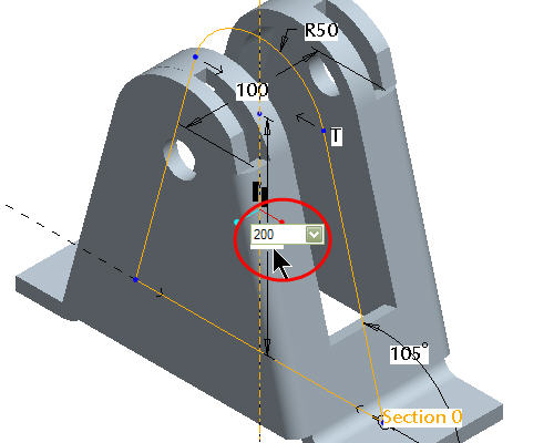
Step 4: Verify the change is propagated downstream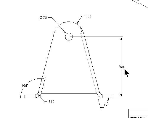
As an alternative to having this open along-side Pro/Engineer, you can also view a printable version by clicking here.
|
Task 1. Browse the Model Structure |
Start Pro/ENGINEER Wildfire 3.0 Tryout Edition if necessary.
In the Navigator Folder Browser ![]() , browse to the following folder C:\HANDS-ON_WF3\INTRODUCTION_TUTORIAL.
, browse to the following folder C:\HANDS-ON_WF3\INTRODUCTION_TUTORIAL.
Right-click the INTRODUCTION_TUTORIAL folder and select Set Working Directory.
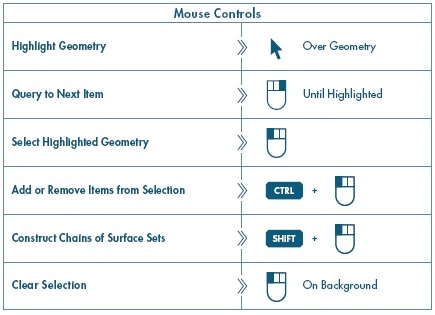
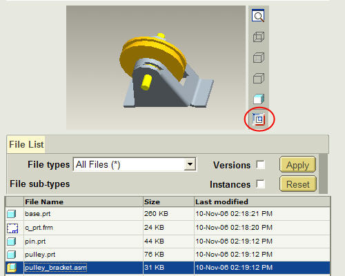
Click PULLEY_BRACKET.ASM from the File List to preview the part. Middle-drag in the preview window to spin the model.
|
|
Middle-drag implies a middle mouse button "press and hold", while moving the mouse. |
Click Open in Pro/E ![]() from the browser as shown in the previous model.
from the browser as shown in the previous model.
When the assembly opens, notice the model structure. The assembly contains three parts namely BASE.PRT, PULLEY.PRT and PIN.PRT.
Right click on the BASE.PRT and click Open.
|
Task 2. Viewing and selection on the models |
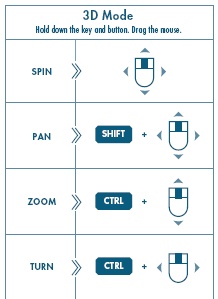
With the BASE.PRT open, MIDDLE-DRAG in the graphics window to spin the model. Spin the model in several directions and notice the model is spinning around the spin center in the center of the model.
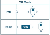
Press SHIFT + MIDDLE-DRAG to pan the model from the center of the graphic window.
|
|
The '+' indicates that the keys are held down simultaneously. |
To Zoom in, press CTRL + MIDDLE-DRAG vertically toward you.
To Zoom out, press CTRL + MIDDLE-DRAG vertically away from you. If you have a wheel mouse. Roll the mouse wheel toward you to zoom in an roll the mouse wheel away from you to zoom out.
Click CTRL + D to return the model to the default position.
In the model tree, right click on the feature called PROTRUSION and select Edit.
The dimension will appear for the protrusion on the model.
Double-click on the vertical dimension of 155 and type 250 and click ENTER.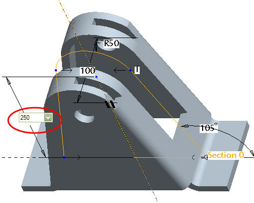
Click Regenerate ![]() from the main toolbar to incorporate the changes.
from the main toolbar to incorporate the changes.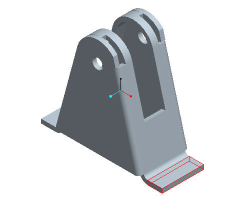
Click Save ![]() from the main toolbar.
from the main toolbar.
Click File > Close Window ![]() .
.
|
Task 3. Verify the change in the drawing |
Click Regenerate ![]() from the main toolbar to incorporate the changes in the assembly.
from the main toolbar to incorporate the changes in the assembly.
Click Open ![]() from the main toolbar.
from the main toolbar.
Select on PULLEY_BRACKET.DRW and click Open.
To Pan to the changed dimension, click middle-drag and select the view shown below.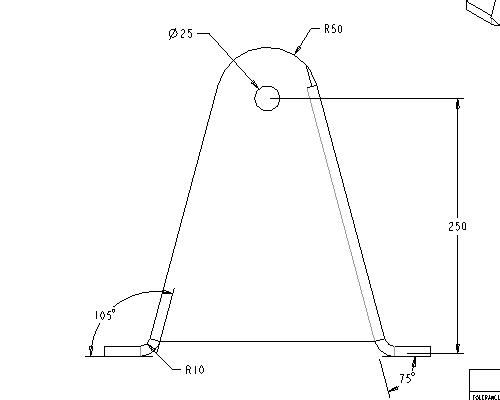
To Zoom in, click CTRL + MIDDLE-DRAG vertically toward you.
Click File > Close Windows .
Spin and zoom in the model to observe the change in the model.
Click Save ![]() from the main toolbar and OK.
from the main toolbar and OK.
To clear the models from RAM, click File > Erase > Current.
Press Select All ![]() and OK.
and OK.
Congratulations! This completes the workshop.