This tutorial teaches the basic process of how to create a simple assembly of existing parts inside of Pro/ENGINEER.
Task 1: Create a new Assembly.
Task 2: Assemble the transmission case as the base component using the default constraint.

Task 3: Assemble the belt drive pulley using two constraints.
Task 4: Assemble the transmission cover using three constraints.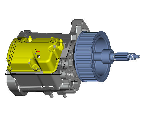
Task 5: Assemble the washer to the transmission cover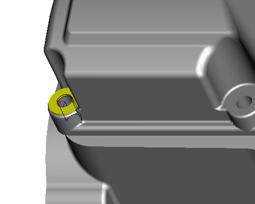
Task 6: Place additional washers using a pattern.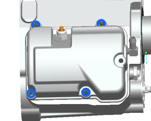
Task 7: Assemble the hex bot with predefined constraints.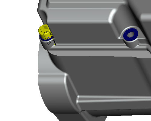
Task 8: Place additional hex bolts using a pattern.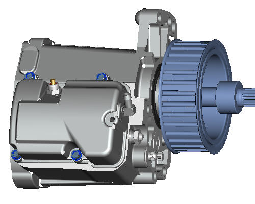
Start Pro/ENGINEER Wildfire 4.0 Schools Edition if necessary.
If Pro/ENGINEER is already running, close all windows then remove all objects from session using File > Erase > Not Displayed...
File > Set Working Directory... , and browse to HANDS-ON_WF4\06-ASSEMBLY.
Click New ![]() icon from the main toolbar.
icon from the main toolbar.
In the New dialog box, select Assembly radio button and type EXAMPLE.
Click OK from the dialog box.
|
|
Default templates are used when a new part or assembly is created. The default template is an initial design model that contains default features, layers, views, parameters and units. |
|
|
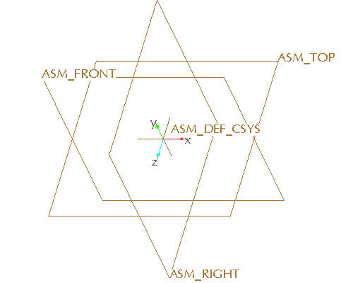
Component Placement is based on placement definition sets. The first component placed is called the base component. Other components may reference this component or the assembly features. The transmission case part will be assembled as the base component. |
Click Datum Planes ![]() , Datum Points
, Datum Points ![]() , Datum Axes
, Datum Axes ![]() and Coordinate Systems
and Coordinate Systems ![]() in the main toolbar to toggle their display.
in the main toolbar to toggle their display.
Select Component Assemble ![]() icon on the right side toolbar.
icon on the right side toolbar.
In the dialog box, select the TRANSMISSION_CASE.PRT and select Open. The new component will appear in yellow on the screen as shown below.
|
|
The preview button in the file open dialog box will show a graphical preview for the selected Pro/ENGINEER object using ProductView Express. |
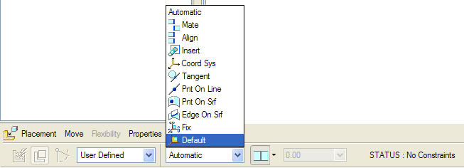
In the assembly dashboard at the bottom of the screen, display the constraint list by clicking Automatic or the adjacent arrow and select Default constraint.
|
|
Default constraint places the component at the assembly origin by aligning the default coordinate system of the component to the default coordinate system of the assembly. |
|
|
In the Component placement dashboard, the component STATUS will report if the component is FULLY CONSTRAINED, PARTIALLY CONSTRAINED, INVALID CONSTRAINTS or NO CONSTRAINTS. A component is FULLY CONSTRAINED when its placement is defined in all the required degrees of freedom. As long as the constraints are valid, the component can be Package with incomplete constraints. |
Select Complete Component ![]() to complete the assembly of the case.
to complete the assembly of the case.
|
|
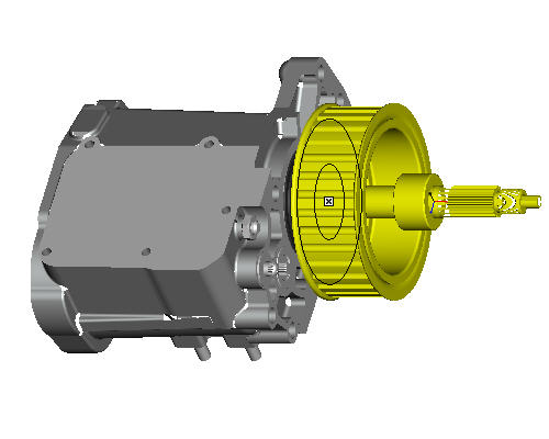
The belt drive pulley will be assembled by aligning the pulley shaft to the output shaft of the transmission and mating two surfaces. Only two degrees of freedom are defined for the component to be FULLY CONSTRAINED since the pulley shaft and the output shaft are free to rotate. |
Select Component Assemble ![]() icon in the right side toolbar.
icon in the right side toolbar.
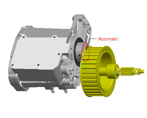
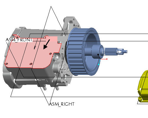
From the Open dialog box, select BELT_DRIVE.PRT as the part to assemble and select Open. The belt drive model will appear in the graphics window in yellow to represent the part being assembled.
Left click on the outside surface of the output shaft of the transmission as shown in the figure below. Notice the surface selected is in red with the "automatic" note pointing to the surface.
|
|
To select a surface, move the cursor over the surface until it turns blue. Then select the surface using the left mouse button. |
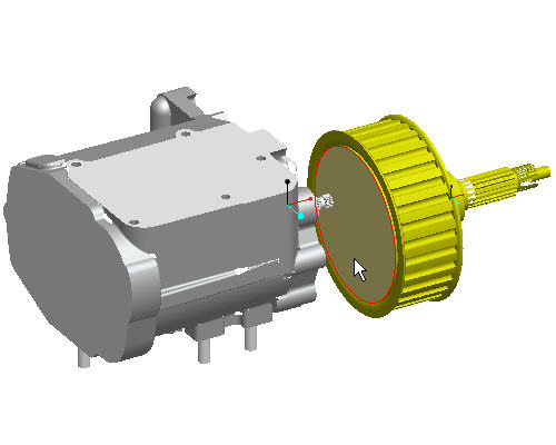
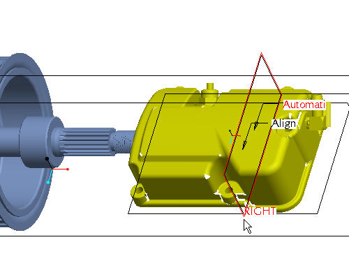
MIDDLE-DRAG in the window to spin the model to an orientation similar to the figure below.
|
|
Middle-drag implies a middle mouse button "press and hold", while moving the mouse. |
Left click on the surface on the belt drive part as shown in the figure below.
|
|
The Automatic constraint will automatically select the appropriate constraint type based on the references selected on the component and the assembly. |
Notice that the belt drive part is mated with the output shaft of the transmission however the component is not fully constrained.
Select CTRL + D to reorient the model into the default orientation.
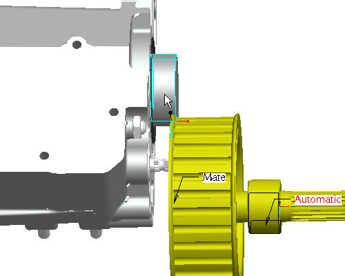
Select the cylindrical surface on the drive pulley as shown in the figure below.
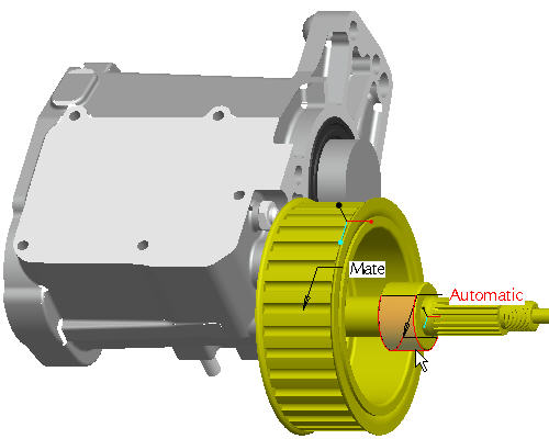
Orient the model to better select the cylindrical surface of the output shaft on the transmission case. Roll the scroll button toward you to zoom in. Use SHIFT + MIDDLE-DRAG to pan the model to the center of the screen. Use MIDDLE-DRAG to rotate the model.
Select the cylindrical surface of the output shaft from the transmission case as shown in cyan in the figure below. Notice how the automatic constraint aligns the two shafts together.
Select Complete Component ![]() in the dashboard.
in the dashboard.
|
|
Select the Placement tab in the dashboard to review or reselect an existing constraint type and the references on the component or the assembly. |
Select Repaint ![]() icon from the main toolbar.
icon from the main toolbar.
Select CTRL+D to reorient the model into the default orientation.
|
|
The transmission cover will use three placement constraints to FULLY CONSTRAINED the component in all three degrees of freedom. |
Click Datum Planes ![]() in the main toolbar to display the datums for assembly.
in the main toolbar to display the datums for assembly.
Select Component Assemble ![]() icon in the right side toolbar.
icon in the right side toolbar.
From the Open dialog box, select TRANSMISSION_COVER.PRT as the part to assemble and select Open. The transmission cover model will appear in the graphics window in yellow to represent the part being assembled.
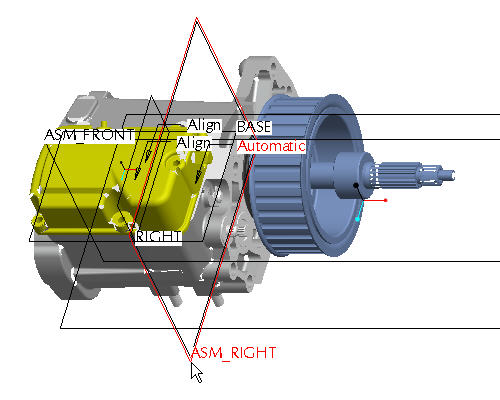
Select the BASE datum plane for a reference on the cover as shown in the figure below.
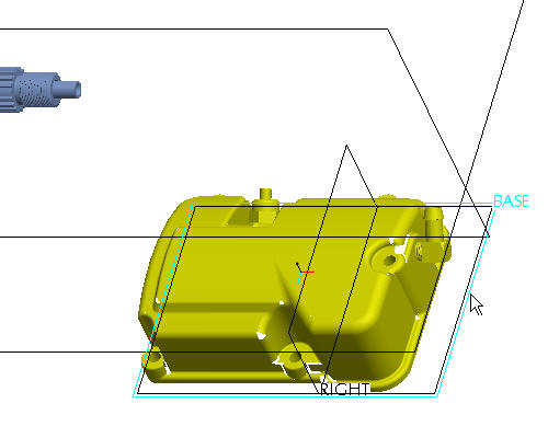
Select the top of the transmission case to align to as shown in the figure below. Notice how the part has now moved to align the selected surfaces as the first constraint.
Select the RIGHT datum plane on the cover as shown in the figure below.
Select the ASM_RIGHT datum plane to as shown in the figure below. Notice how the cover now snaps over into alignment as the second constraint.
Click Datum Planes ![]() in the main toolbar to display the datums for assembly.
in the main toolbar to display the datums for assembly.
|
|
The |
Select Component Assemble ![]() icon in the right side toolbar.
icon in the right side toolbar.
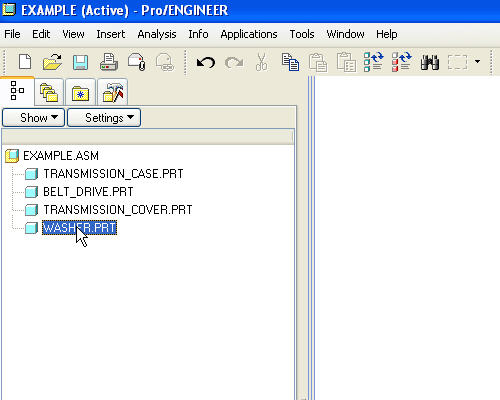
From the Open dialog box, select WASHER.PRT as the part to assemble and select Open. The washer model will appear in the graphics window in yellow to represent the part being assembled.
|
|
The component can be moved independent of the assembly model by using the following mouse and key combinations:
|
Press and hold both the CTRL+ALT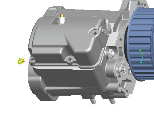
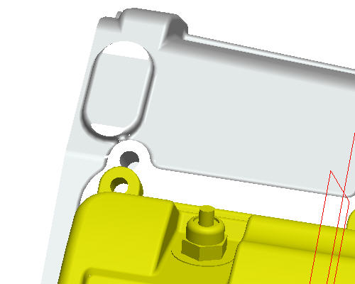
Orient the model to better select the lower left hole on the transmission cover. Roll the scroll button toward you to zoom in. Use SHIFT + MIDDLE-DRAG to pan the model to the center of the screen. Use MIDDLE-DRAG to rotate the model.
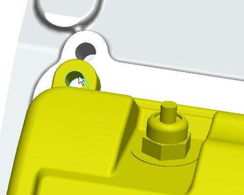
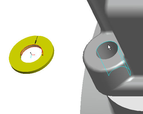
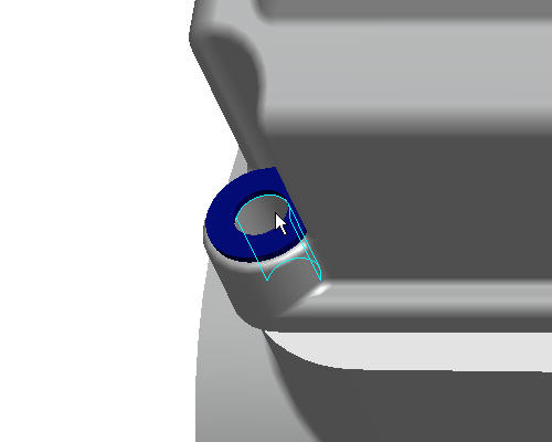
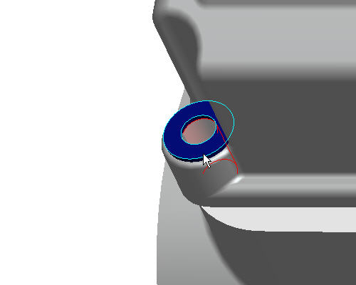
Select the inside cylindrical surface of the washer as shown in the figure below.
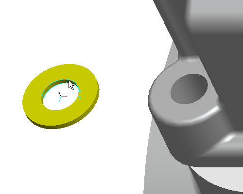
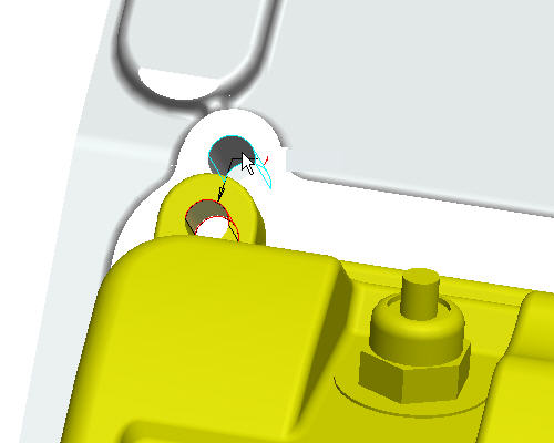
Select the cylindrical surface of the hole in the transmission case as shown below. The washer should now be in line with the hole as the first constraint.
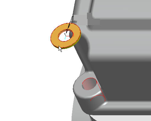
Select the top surface of the hole on the transmission cover as shown below. Notice how the washer has been placed inside the cover due to the top of the washer being aligned to the top of the cover.
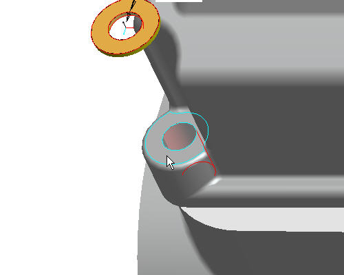
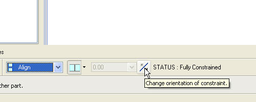
Select the Component Placement Flip ![]() icon from the dashboard to change the constraints orientation. Notice how the washer has now been flipped over and is in the correct orientation.
icon from the dashboard to change the constraints orientation. Notice how the washer has now been flipped over and is in the correct orientation.
Select Complete Component ![]() from the dashboard.
from the dashboard.
Select Repaint ![]() icon on the main toolbar.
icon on the main toolbar.
Select CTRL+D to reorient the model into the default orientation.
|
|
The washer needs to be placed in all 4 hole locations on the transmission cover. This can be done by patterning the washer. |
Left click washer part from the model tree as shown in the figure below. The washer should highlight in red in the graphics window.
Press and hold Right click and select Pattern from the pull down menus.
The Pattern dashboard default pattern type is Reference which references the pattern of the holes on the transmission_case. Notice that black dots have been created where the washer will be patterned.
|
|
Pro/ENGINEER has the ability to store common assembly references into existing parts to ease in the assembly process. |
Select Component Assemble ![]() icon in the right side toolbar.
icon in the right side toolbar.
From the Open dialog box, select HEX_BOLT.PRT as the part to assemble and select Open. Notice that when the bolt appears in the assembly, there are already assembly reference tags on the bolt (insert, mate).
|
|
The bolt was predefined with component interface information stored with the part. |
Orient the model to better select the lower left hole on the transmission cover. Roll the scroll button toward you to zoom in. Use SHIFT + MIDDLE-DRAG to pan the model to the center of the screen. Use MIDDLE-DRAG to rotate the model.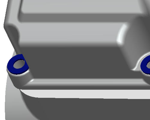
Select the cylindrical surface of the bolt hole as shown in the figure below.
Select the top surface of the washer as shown in the figure below to complete the placement. Notice how the bolt snaps into place without selecting any references on the bolt.
Select Complete Component ![]() from the dashboard.
from the dashboard.
Select Repaint ![]() icon on the main toolbar.
icon on the main toolbar.
Select CTRL+D to reorient the model into the default orientation.
|
|
Like the washer, the hex bolt needs to be placed in all 4 hole locations on the transmission cover. This can be done by patterning the bolt. |
Left click HEX_BOLT part from the model tree as shown in the figure below. The hex_bolt should highlight in red in the graphics window.
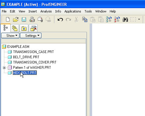
Press and hold Right click and select Pattern from the pull down menus.
The Pattern dashboard default pattern type is Reference which references the pattern of the holes on the transmission_case. Notice that black dots have been created where the bolt will be patterned.
Select Complete Feature ![]() from the dashboard to accept the default pattern. Notice that four bolts now exist in the assembly as shown below.
from the dashboard to accept the default pattern. Notice that four bolts now exist in the assembly as shown below. 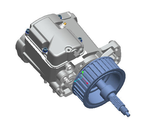
Click Save ![]() from the main toolbar.
from the main toolbar.