Creating Alternate Structures in a New Product
When starting with a new CAD design, multi-part alternates can be created from an initially built structure by using the Edit Associations action.
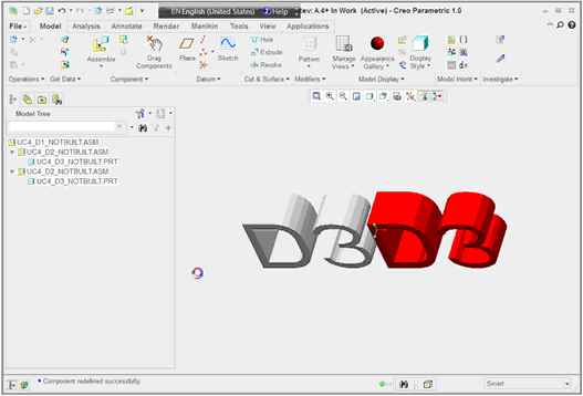
In this example, a single CAD structure is set up to drive two Windchill part structures. The following figure shows the CAD structure within Creo.
In Creo, it can be helpful to set up feature name display in the model tree. This indicates which subassembly is on the left or right, as shown in the following colorless Creo model. 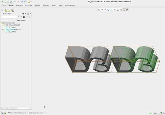 |
To create multiple part alternates driven by a single CAD model:
1. Create an initial part structure by performing a Check In with the Auto Associate Parts to CAD Documents action selected, and with the server-side preference Build After Check In set to All.
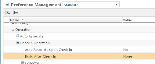
2. Now set the Build After Check In preferences to None as shown in the following figure.
3. In the workspace, select a CAD document, and then select > to create/associate other multi-owner parts. For example, you can select D3 (which initially has a red part alternate) and click the new part icon. to create a white and then a green alternate as shown in the following figure.
to create a white and then a green alternate as shown in the following figure.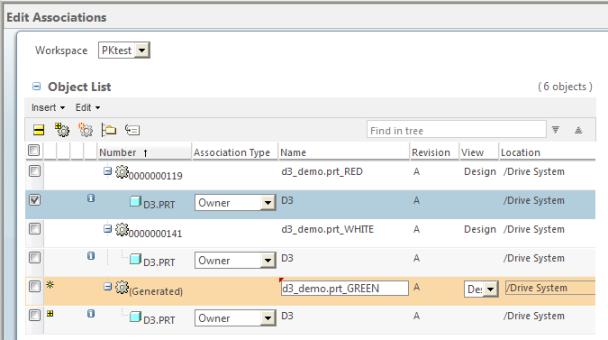
New alternates display in the Parts table on the Related Objects tab of the CAD model’s information page.
The order in which the associations are created determines which of the multi-owner Windchill parts is assigned “primary owner-associated part” status for purposes of representation management by Windchill Visualization Services. A part with primary status shares the same representation with its associated CAD document. For example, if you do a mark-up on the CAD Document, it shows on the primary part. If only one part is built, it becomes primary. However, when multiple owner-associated Windchill parts for the CAD document are built, then the first one associated becomes primary, and the rest are considered non-primary. In the current Edit Associations and Auto Associate Parts user interfaces, when multiple Windchill parts are simultaneously specified as owner for a CAD document, clicking OK randomly chooses one part to be the primary part. In order to assure that your preferred part receives primary designation, use the following procedure. 1. First associate your preferred part as the owner of the CAD document. The part receives primary designation. 2. In a subsequent association activity, make the additional owner associations to the remaining part or parts. If desired, managed representations can be copied to non-primary parts by setting the preferences Visualization>Copy Representations to Described Parts>Enabled to Yes, and Visualization>Copy Representations to Described Parts>Navigation> to Non-primary owner associations. For more information, see Representations of CAD Documents with Owner-Associated Parts. |
Working with Multi-owner Structures
With the introduction of multi-owner associations, there are new complexities to consider. Previously, when comparing CAD and part structures, there was no ambiguity about which part structure to use. However, when using multi-part functionality, the following changes to previous functionality are required.
• First, Check In must be configurable so that part structure can be set to not automatically attempt to build upon check in and instead controlled by the preference Build After Check In. As noted previously, to allow multiple owner parts, the first requirement is to allow Check In to be configurable, so that part structure can be set to not automatically attempt to build upon check in; instead, whether to build or not build upon check in is controlled by a preference Build After Check In.
• Second, a user interface is required to enable user selection of the correct part structure. This selection begins in the Compare CAD Document to Part user interface.
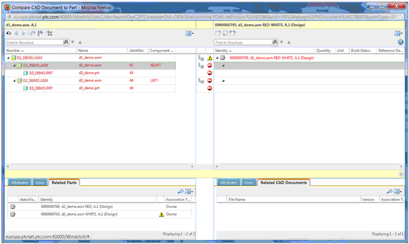
In this example, a structure with all RED components has been built, using check in with auto associate and the preference set to build on check in. The RED-WHITE structure is “empty” (CAD-associated parts have been created using Edit Associations, but no part structure is yet built), and will be constructed by selecting the appropriate preferred parts.
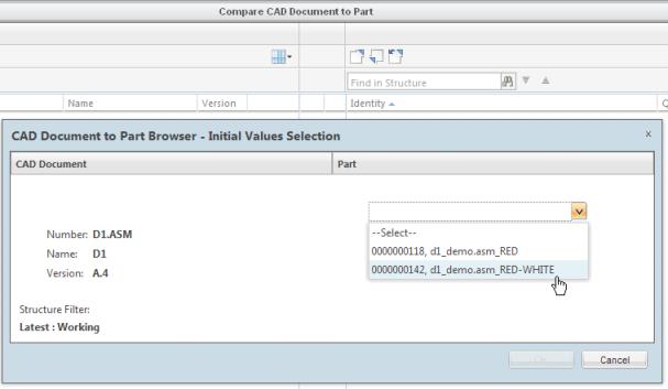
1. Start the comparison by identifying which top part assembly to compare to CAD.
The pull-down menu appears only in a multi-owner situation. In this case, select to compare the currently unbuilt RED-WHITE part structure as shown in the following figure.
D2_Demo has both a RED and WHITE part subassembly

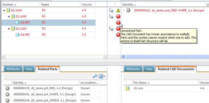
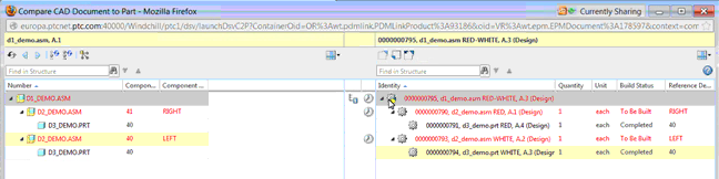
The CAD part D3 has three associated Windchill parts as shown in the following figure.
The remaining components of D1.asm are the same D2 and D3.
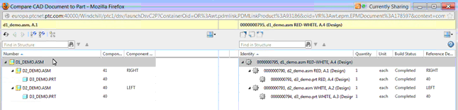
2. Resolve the Windchill parts for the d1_demo.asm RED-WHITE part structure.
When in a multi-owner environment, a new user interface action allows resolution of the part ambiguity using the Select a preferred part to use when building Part structure button.

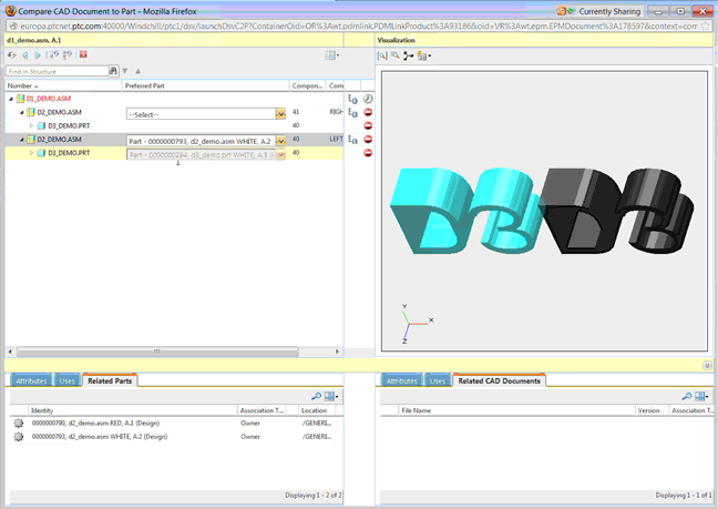
When the new action button is selected, a Preferred Part column with pull-down menus listing the available parts to select from (owner-associated parts only) is added to the CAD-side table of the Compare CAD Document to Part window, as shown in the following figure.

A Visualization panel also appears on the right that enables you to cross-highlight and orient as to which subassembly is which.
In the following example, the goal is to create a structure with WHITE on the left and RED on the right.
The Preferred Part column can be made wider to show full part identities. (out-of-the-box, the definition of Identity is <Type, Number, Name, Version>.). For the left D2 subassembly, select the WHITE alternate. |
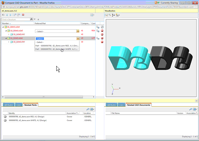
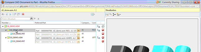
Upon selection of the D2 WHITE preferred part, note that the Preferred Part pull-down menu is now not editable because the part has already been built. If the D2 WHITE preferred part had not been built previously, there would be a selection offered in the pull-down for the D3 part.
Similarly, for the right subassembly, the D2 RED alternate is selected.

In addition to using the part identifier or the Visualization pane for selecting the preferred part, you can use table management in the Related Parts tab table to add columns containing distinguishing attributes, as needed. |
3. Now that the structure is resolved, click Exit Resolve Part to return to the Compare CAD Document to Part window.
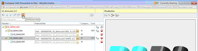
As the Preferred Part selections are used to edit the part structure, upon exiting resolve part, a Confirmation message is presented. Selecting Yes checks out the top part assembly D1 and Uses links are added to the D2 RED and D2 WHITE subassemblies.
The part is kept in a checked-out state to:
◦ allow inspection, or perhaps modification.
◦ allow completion.
4. When satisfied with the part structure, the next step is to finalize the part structure by selecting D1 and clicking the build multi-level part structure icon 
After the part structure is built, the structure automatically builds in the future. Note that the automatic build is not affected by a change in quantity, geometry, or attributes. It is, however, affected by the addition of other multi-owner parts to the assemblies. After a build, the CAD document is published again and viewables are shared.
In this early implementation, there are known issues affecting the part to CAD document comparison that PTC plans to address in a future release. Compare Part to CAD Document is not part of a primary use case. |