Visualization Tab
The
Visualization tab displays the visual representation for all parts defined in the product structure. The visual representation is generated from the related CAD data associated with the part using the
WindchillVisualization Services. In
Windchill, Creo View WebGL Viewer replaces Creo View as the default embedded 3D model viewer technology in Visualization tab for users of Firefox, Google Chrome and Microsoft Edge browsers. The client system no longer requires Creo View installed in order to enable the display of visual representations through these browsers. Creo View WebGL Viewer renders 3D graphics only.
For users of Internet Explorer browser, Creo View is the default embedded 3D model viewer technology in Windchill. Use of Creo View WebGL Viewer is not recommended as it is incompatible with Internet Explorer.
If you want to revert to using the Creo View plug-in for Firefox ESR 52 (32-bit), contact your administrator.
|
|
Web browsers are moving away from plug-in support. A new mechanism, WebGL may be implemented in your enterprise to view representations in applications such as the Thumbnail Navigator, Thumbnail Viewer, and Visualization tab.
If it is implemented, you can select SHIFT+P to change browser preferences available to you. For more information about the Creo View WebGL Viewer, refer the topic Creo View WebGL Viewer. |
For more information about this configuration, see the online help topic
Windchill Visualization Service Properties.
Tab Display
The display of the
Visualization tab is controlled by the following
preference: > . The
Visualization tab displays only when this preference is set to
Yes.
The Visualization tab does not display if using Windchill on a Macintosh operating system.
Loading Visual Representations
The following
preference determines how visual representations load in the
Visualization tab: > . When this preference is set to
Yes,
Visualization tab geometry does not display by default. Instead, you use checkboxes in the structure pane to load or clear the visual representations of the parts that display in the
Visualization tab.
For assemblies, checkmarks display when all component parts are selected and the assembly has a viewable. Squares display when some, but not all, component parts are selected. Squares also display when the assembly or any component parts do not have a viewable.
|
|
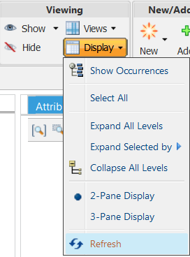
When using incremental loading, if an object is checked in or checked out in the structure, refresh the Visualization tab to ensure the tab is in sync with the structure. Use the browser page refresh or the Refresh action available in the structure toolbar as shown below. |
Icons
The images in the Visualization tab serve two purposes:
• Visual verification of parts selected the part structure.
• Ability to filter the part structure using a volume.
The icons above the visualization area control the image display. See the table below for descriptions of these actions which are common to Creo View WebGL Viewer and Creo View:
|
Icon
|
Action Name
|
Description
|
|
Zoom All
|
Re-sizes all images to fit the visualization window.
|
|
Zoom Selected
|
Re-sizes a selected image to fill the visualization window.
|
|
Zoom Window
|
Expands a selected area to fit the graphics area.
|
|
Icon
|
Action Name
|
Description
|
|
Set Spin Center
|
Selects a screen location about which the image may be revolved.
|
|
Toggle the Automatic Selection Preferences
|
Used to specify the selection behavior between the part structure pane and visualization image. Contains a menu with the following choices:
• Automatically Select from Structure to Visualization – When checked, selecting a part in the part structure pane causes the corresponding part image to be highlighted in the visualization tab.
|
|
Only supported for parts selected one at a time or multiple selections using the CTRL key. Not supported for parts selected within a range in the structure pane using the SHIFT key.
|
• Automatically Select from Visualization to Structure – When checked, selecting an image in the visualization tab causes the corresponding part to be highlighted in the part structure pane.
|
|
Only supported for images selected one at a time or multiple selections using the CTRL key. Not supported for multiple images selected by dragging a rectangular area in the visualization window.
|
|
|
In a multibody structure, if you click the body node in the Visualization tab, then the parent part of the selected body is highlighted in the structure.
|
|
|
Spatial Filter
|
Used to define a part structure filter based on geometric volumes. Contains a menu with the following choices:
• Set Box Spatial Filter – A filter created to include all parts with volumes that reside completely within or partially intersect a specified cube. For more information, see Box Spatial Filters.
• Set Sphere Spatial Filter – A filter created to include all parts with volumes that reside completely within or partially intersect a specified sphere. For more information, see Sphere Spatial Filters.
• Set Proximity Spatial Filter – A filter created to include all parts with volumes that reside completely within or partially intersect a the volume drawn around a selected part. For more information, see Proximity Spatial Filters.
• Update Spatial Filter – Allows the user to modify the parameters of an existing spatial filter.
|
|
Spatial filters can also be defined from the Edit Filter icon on the toolbar of the Structure tab. For more information about using spatial filters, see About Spatial Filters. |
|
|
Spatial Rule
|
Available for Configuration Context only. Opens a menu to set or update a box, sphere, or (where a component is selected) proximity spatial rule.
For more information about using spatial rules, see the following topics.
|
|
Icon
|
Action Name
|
Description
|
|
Orientation
|
Used to determine display direction. Contains a menu with the following options: •  — ISO 1 •  — ISO 2 •  — Top •  — Bottom •  — Left •  — Right •  — Front •  — Back |
|
Icon
|
Action Name
|
Description
|
|
Select Mode
|
Highlights individual parts or multiple parts for inspection. Clears previously highlighted parts.
|
|
Select All
|
Highlights all parts for inspection.
|
|
Icon
|
Action Name
|
Description
|
|
Rotate and Transform Mode
|
A combined dragger for translating and rotating parts
|
|
Restore Location
|
Used to return the parts to their original locations. Contains a menu with the following choices:
• Restore all to original– Restores all parts to their original position and orientation.
• Restore selected to original– Restores the selected parts to their original position and orientation.
|
Render mode, available in Creo View only, modifies the appearance of the figure. The menu contains the following options:
|
Icon
|
Action Name
|
Description
|
|
Shaded
|
Used to display the part as a solid gradient
|
|
Shaded with Edges
|
Gradient appearance. The outlines of forward surfaces are emphasized.
|
|
This option is not available in PSB.
|
|
|
Hidden line removal
|
Only black outlines of the forward surfaces
|
|
Wireframe
|
Displays front and back frame lines equally
|
|
Mesh
|
Displays a mesh frame
|
Measurement tools, available in Creo View only, allow measuring the distance, diameter and angle between two entities. The menu contains the following options:
|
Icon
|
Action Name
|
Description
|
|
Create a Distance Measurement
|
Measures the distance between two or more entities.
|
|
Create a Diameter Measurement
|
Measures the diameter or radius of a selected entity.
|
|
Create an Angle Measurement
|
Measures the angle between two linear entities.
|
|
Create a Summary Measurement
|
Allows you to define your own quantities of measure and override existing display units. Windchill supports over 40 standard quantities of measure. New quantities of measure can also be created.
|
|
Icon
|
Action Name
|
Description
|
|
Delete Selected Measurement
|
Used to delete the selected measurement.
|
|
Delete All Measurements
|
Used to delete all measurement.
|