|
|
2D illustrations of a type not supported by your browser display as a Creo View icon. Clicking on the icon attempts to open the image in a Creo View plugin.
|
|
|
2D illustrations of a type not supported by your browser display as a Creo View icon. Clicking on the icon attempts to open the image in a Creo View plugin.
|
|
|
WebGL is not provided for Internet Explorer.
|
|
|
When using incremental loading, if an object is checked in or checked out in the structure, refresh the Visualization tab to ensure the tab is in sync with the structure. Use the browser page refresh or the Refresh action available in the structure toolbar as shown below. 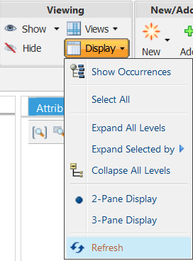 |
|
Icon
|
Action Name
|
Description
|
 |
Zoom all
|
Re-sizes all images to fit the visualization window.
|
 |
Zoom selected
|
Re-sizes a selected image to fill the visualization window.
|
 |
Zoom window
|
Expands a selected area to fit the graphics area.
|
|
Icon
|
Action Name
|
Description
|
||||
 |
Set spin center
|
Selects a screen location about which the image may be revolved.
|
||||
 |
Toggle the automatic selection preference
|
Specifies the selection behavior between the parts list structure pane and visualization image.
• Automatically Select from Structure to Visualization – When checked, selecting an item in the parts list structure pane causes the corresponding image to be highlighted in the visualization tab.
• Automatically Select from Visualization to Structure – When checked, selecting an image in the visualization tab causes the corresponding item to be highlighted in the parts list structure pane.
These features require links between the parts list structure and the visualization, created with Link Item.
|
||||
 |
Spatial filter
|
Used to define a structure filter based on geometric volumes:
• Set Box Spatial Filter – A filter created to include all parts with volumes that reside completely within or partially intersect a specified cube.
For more information, see Box Spatial Filters.
• Set Sphere Spatial Filter – A filter created to include all parts with volumes that reside completely within or partially intersect a specified sphere.
For more information, see Sphere Spatial Filters.
• Set Proximity Spatial Filter – A filter created to include all parts with volumes that reside completely within or partially intersect a the volume drawn around a selected part.
For more information, see Proximity Spatial Filters.
• Update Spatial Filter – Allows the user to modify the parameters of an existing spatial filter.
|
|
Icon
|
Action Name
|
Description
|
 |
Shaded
|
Used to display the part as a solid gradient
|
 |
Orientation
|
Determines display direction: •  — ISO 1 — ISO 1•  — ISO 2 — ISO 2•  — Top — Top•  — Bottom — Bottom•  — Left — Left•  — Right — Right•  — Front — Front•  — Back — Back |
|
Icon
|
Action Name
|
Description
|
 |
Select mode
|
Highlights individual parts or multiple parts for inspection and clears previously highlighted parts
|
 |
Select all
|
Highlights all parts for inspection
|
|
Icon
|
Action Name
|
Description
|
|
Rotate and Transform mode
|
A combined dragger for translating and rotating parts
|
|
|
Transform mode
|
A combined dragger for translating and rotating parts
|
|
 |
Free rotation mode
|
Rotates in the selected direction
|
 |
Restore location
|
Return parts to their original locations
|
|
Icon
|
Action Name
|
Description
|
 |
Create a distance measurement
|
Measures the distance between two or more entities
|
 |
Create a diameter measurement
|
Measures the diameter or radius of a selected entity
|
 |
Create an angle measurement
|
Measures the angle between two linear entities
|
 |
Create a summary measurement
|
Allows you to define your own quantities of measure and override existing display units
Windchill supports over 40 standard quantities of measure. New quantities of measure can also be created.
|
|
Icon
|
Action Name
|
Description
|
 |
Delete selected measurement
|
Used to delete the selected measurement.
|
 |
Delete all measurements
|
Used to delete all measurement.
|
|
Icon
|
Action Name
|
Description
|
 |
Link Item
|
Creates a link between a part in the parts list structure tree and the corresponding part in the visualization. Select a part in both the visualization and the tree and click Link Item.
Required to support the Automatically Select from Structure to Visualization and Automatically Select from Visualization to Structure options.
|
 |
Display Illustration
|
Lists the illustrations available in the parts list structure for selection and display in the visualization area
For more information, see Add an Illustration to a Parts List.
|