Add a Phantom View to the Model
Adding a phantom view to a part can be thought of as the opposite of highlighting a part. Phantom views are used when a particular part needs to be clearly visible within the context of an assembly. Phantom views can be added at any step in an illustration sequence and are commonly found in AR experiences for startup and repair procedures. Use the following steps to learn how to add a phantom view to most of the quadcopter and show only the essential parts for a repair procedure. These effects are added to edit the appearance of the model before the repair sequence starts.
When completed, the .pvz file from Creo Illustrate will include a phantom view and disassembly sequence (created in the next section). When the .pvz file is uploaded into Vuforia Studio, the result will look like the images below. The first image is of the first step of the sequence; all the parts are at the same color saturation level. The second image shows the second step where all parts with a phantom effect are visibly toned down. In the second step, the front right motor and rotor are highlighted as a repair sequence is starting.
1. ROTOR.PRT and MOTOR.PRT in the frontleft subassembly in the lift subassembly are the intended visible parts. All other parts will be phantom.
2. Right-click inside the sBOM tab in the primary panel. Select Expand and then All. This expands the model tree to show all parts of the model.
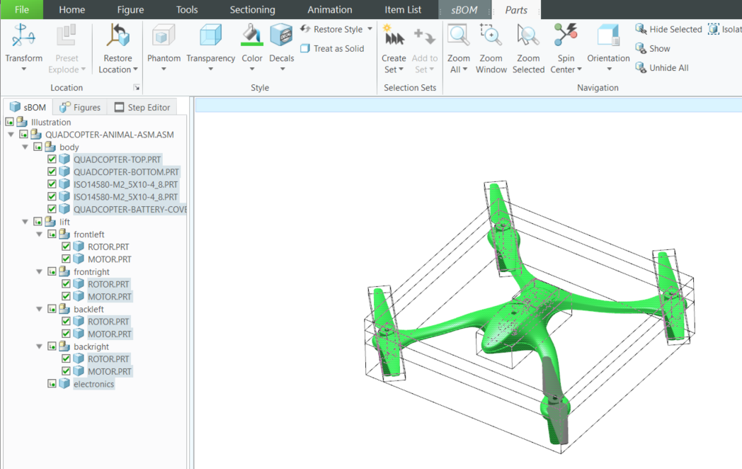
3. In the sBOM tab, select all parts except for the rotor and motor in the frontleft assembly so that the model looks like the image below.
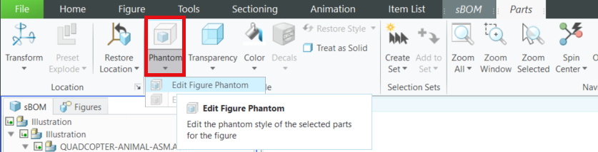
4. With the parts still selected, navigate to the Parts tab in the ribbon and select > within the Style section. This adds the phantom effect to the selected parts.
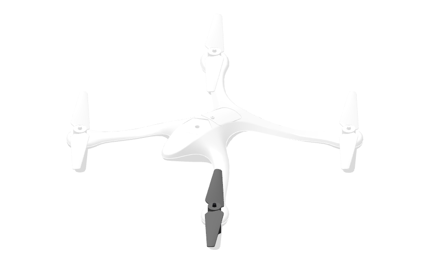
5. If the phantom view was added successfully, the model should look like the image below. Notice that the color of the front left rotor and motor did not change, but the color of all other parts did.