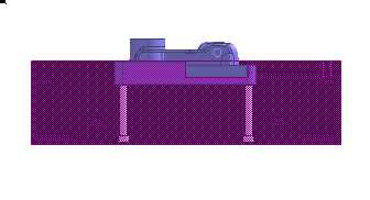
* Hide all the parts except for Core2 and Plate3.
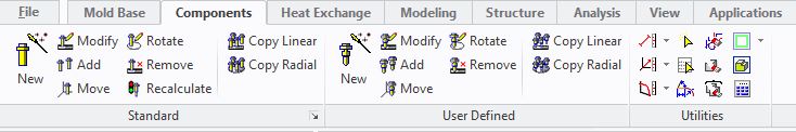
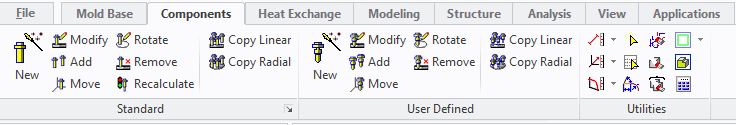
* Click Components tab.
The Standard Components ribbon tab is loaded.
* Click New.
Components dialogue box appears.
* Click Component.
Components browser list appears.
* Select Cap Screw under Screw.
The dialog name changes to Cap Screw indicating the selected component.
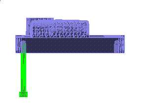
* Select bottom face of plate3 as a start face.
Position dialogue box appears.
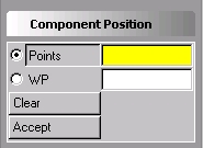
* Click WP.
* Select Screw workplane under Core assembly.
* Click Accept.
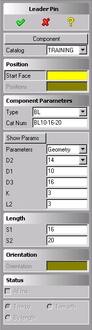
* Click Show Param.
The component graphic help appears.
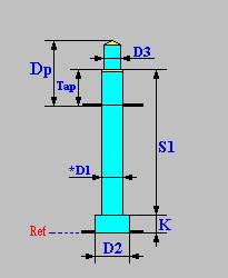
The graphic help defines all the modifiable parameters. Some of the parameters are of geometrical type (screw diameter) and some of functional type (tapping depth). You may scroll a leading parameter (D1 in this case) defining the standard components from the catalogue. If you key-in for the leading parameter data which exists in the catalogue it will also be recognized and all the standard parameters will be retrieved. You may select a standard component by catalogue number from the Catalogue box. You may type in alphanumeric data thereby creating non-standard components.
* Scroll D1 to 8.
* Click S1.
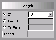
* Scroll S1 to 50.
* Click Accept.
* Click Parameter and change to oversize.
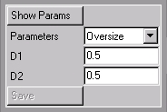
The parameters in this button define the clearance dimensions for the screw holes. D1 = 0.5 means that the diameter of the hole for the screw will be 0.5mm larger then the nominal dimension of the screw. D2 = 0.5 means that the diameter of the hole for the screw head will be 0.5mm larger the nominal diameter of the screw head. You can change the default clearance dimension and click the Save button to save the new values as defaults for subsequent sessions. The save button is disabled as a default. It is strongly recommended that only a system administrator will enable this button. In order to enable the save button type (moldbase-ui::setadmin t) in the Enter Command Line. In order to disable it again type (moldbase-ui::setadmin nil)
* Click .
.
Mold Base issues a warning message indicating that the "Screw Length is Too Short" and allows the option of:
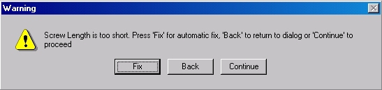
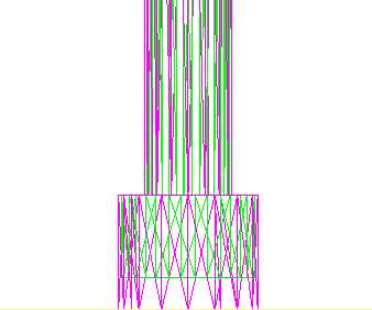
* Click Fix.
The system creates all the relevant holes, with defined clearance dimensions, in Plate3 and in the core insert in one step. Notice that the counter bores for the screw heads were deepened in order to fix the problem of the "short" screw selection.