Spherical UCS
When you create a spherical user defined coordinate system, you specify the
coordinates, which include the origin, the direction of the T = 0 (theta = 0) axis, and the direction of the P = 0 (phi = 0) axis.
Creo Simulate creates the coordinate system as follows:
• Uses the origin and the T = 0 axis location to define the T = 0 axis.
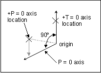
• Makes the P = 0 axis perpendicular to the T = 0 axis and in the plane defined by the origin, the T = 0 axis location, and the P = 0 axis location.
• If you specified a P = 0 axis location that is not on a line perpendicular to the T = 0 axis, Creo Simulate places the positive P = 0 axis in the direction perpendicular to the T = 0 axis that is closest to the location you specified.
The P = 0 axis still lies in the same plane in which you placed it:
The positive P = 90 axis is perpendicular to the other axes with the positive direction determined by the right-hand rule.
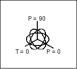
Creo Simulate displays an icon, showing the origin of the new user coordinate system and the direction of each axis.
The orientation of the icon depends on the axes you entered. Here are two views of the icon:


