Example: Orienting the BSCS Shear Center
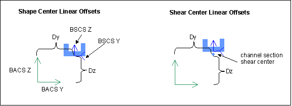
You can choose to shift either the beam shape origin or shear center with the options on the Beam Orientation Definition dialog box. The figures here illustrate the difference in changing the orientation of the shape origin or the shear center with a channel beam section, in which the shear center falls below the shape origin.
In each case below, the left figure shows the change in orientation of the shape origin, and the right figure shows the change in orientation of the shear center. The first figure shows the effect of applying DY and DZ offsets while keeping the orientation angle at zero.
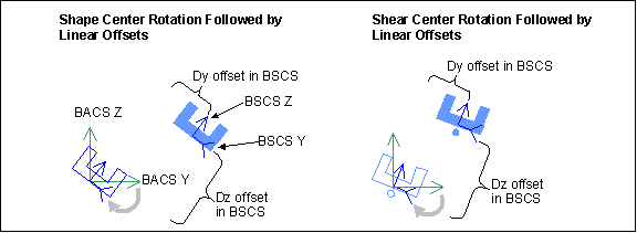
In the next figure, only the orientation angle is changed, causing the BSCS to rotate around the X axis.
In the last figure, both the orientation angle and the DY, DZ offsets have non-zero values. The software performs the rotation first, then translates the BSCS along the rotated BSCS axes to satisfy the DY and DZ offset values.


