Guidelines for Mapped Meshing
While creating a mapped mesh consider the following guidelines:
• Meshing regions are created in a loop mode. When you select edges as references, the two end points of the edges are displayed in the references collector. When you select a surface as a reference, its four vertices are displayed in the reference collector.
• Only mapped mesh controls created at the top level of the assembly influence the mesh. Mapped mesh controls created in subcomponents are ignored.
• If the volume is shell compressed then a mapped mesh control is ignored.
• Since mesh has to be compatible on cyclic symmetry references and mapped mesh regions have fixed number of subdivisions, mesh regions created on the cyclic symmetry references are ignored.
• A mesh region operation may result in merging of existing edge sets. Merged edge set inherits the number of subdivisions from the edge sets to be merged if they have same number of subdivisions, otherwise it has default subdivision. In such case, the left over edge sets are still displayed in the edge set collector. These leftover sub-edge sets inherit the number of subdivisions from the original edge set.
• In Native mode, elements generated in mapped mesh regions are subject to the same edge, face angle and curvature limits that all elements must meet. There is no limit to the curvature of mapped mesh region edges and faces, but the region must have enough subdivisions to allow the element edges and faces to conform to the curvature limits and it is verified only when the mesh is generated, not when the mesh region is defined.
• When mapped meshing controls overlap with other mesh controls, the mapped meshing controls take precedence over the other mesh controls. However, the other mesh controls are still active in the regions of the model where they apply. Also, elements in a mapped mesh that touch a reference of an isolate for exclusion mesh control may be excluded during an analysis, but their size and shape are not affected by the isolate for exclusion mesh control.
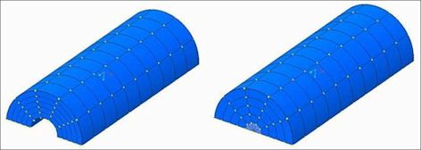
• A semicircular surface is a special case of a triangular or a quadrilateral surface if there is an annular hole. You can create only quadrilateral and triangular meshing regions on semicircular surface regions and cylinder volume regions as shown below:
• When you create a quadrilateral mapped mesh region on a boundary surface of a volume that is meshed with an unstructured mesh, the resulting structured boundary mesh is meshed according to the mapped mesh control while the rest of the boundary and volume is an unstructured mesh. The mapped mesh control produces only triangles. Each of the quads produced by mapped meshing is split into two triangles. The mesher is restricted not to add any more points to the mapped meshed surfaces so that the resulting mesh remains on the boundary surface as dictated by the control. If a shell is on the surface with the mapped mesh control, triangular shell elements are created.
• For assembly models, all the element nodes from one mesh region must coincide and merge with matching element nodes of a neighbouring mesh region. The edges of one mapped region must match and coincide with the corresponding edges of the other mapped mesh region.
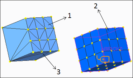
In native mode, AutoGEM creates an unstructured mesh in all regions of the model that do not have a mapped mesh region. The footprint of mapped meshed regions on the boundary of the volume which is to be meshed with an unstructured mesh is retained. The triangles on the footprint of the mapped mesh regions are exactly matched with triangular faces of tetrahedra of the unstructured mesh. The quadrilaterals on the structured mesh are matched with two triangular faces of tetrahedra on the unstructured mesh with an automatic tri-quad link. The exploded view of a model that contains both mapped mesh regions and unstructured mesh regions is shown in the following figure:
1. quadrilaterals on the footprints of a mapped mesh region
2. component with structured mapped mesh
3. component with unstructured mesh
1. triangular faces of tetrahedral on the unstructured mesh
2. component with structured mapped mesh
3. component with unstructured mesh
• FEM mesh regions can be created only on quilt surfaces.
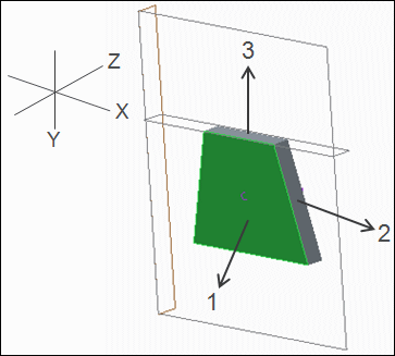
• When you create a mapped mesh region in a 2D model, make sure that the primary surface used for the mapped mesh lies within the XY plane of the referenced coordinate system. Also the surface must be a part of the 2D model.
In the following example, you can create a mapped mesh region only for surface 1 since it is inside the XY plane.
1. surface contained in the XY plane.
2. surface outside the XY plane
3. surface outside the XY plane


