Example: Bonding Elements
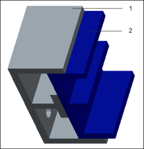
Figure 1 displays an assembly consisting of two parts –1 and 2, displayed in two different colors.
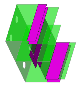
Shell pairs are defined for both the parts. During meshing and analysis, Creo Simulate compresses the pairs to midsurfaces as shown in figure 2.
|
Fig. 1 1. Part 1 2. Part 2 |
Fig. 2 |
|
|
 Note that shell pairs are not a good idealization for these parts because these parts are thick. But they are used in this example so that bonding elements can be distinctly displayed in the figure. |
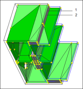
The following figures show the assembly after AutoGEM meshing. By default, Creo Simulate creates bonding elements to link the two parts in the assembly. Figure 3 shows the bonding elements in gray. The shell elements are in green. The two parts in the assembly are assigned different temperature dependent materials. Two bonding elements are created across the thickness of the shell pairs. Each bonding element inherits the material properties and the temperature distribution from its corresponding parent component.
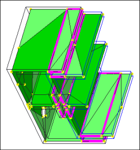
If you clear the Create bonding elements check box on the Settings tab of AutoGEM Settings dialog box, Creo Simulate does not create bonding elements for the assembly during AutoGEM meshing. Figure 4 shows an assembly without bonding elements.
|
Fig. 3 1. Bonding element for part 1 2. Bonding element for part 2 |
Fig. 4 |
The following figures display the assembly in result window. While defining the result window, Fringe is selected as the Display type on the Result Window Definition dialog box.
When you select the Show Bonding Elements check box on the Display Options tab of the Result Window Definition dialog box, the model appears as displayed in the Figure 5. The bonding elements appear in gray in the result window and do not display any fringes or contours of the result quantity. If you do not select the Show Bonding Elements check box, the model appears as displayed in the Figure 6.


