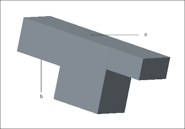
Example: Part with Unopposed Surfaces
The part in the figure below is an example of geometry that can lead to unopposed surfaces in a shell model.
The top of the part, surface a, is selected first for the shell pair. There are three shorter, non continuous surfaces opposite and parallel to surface a. Suppose you select only surface b on the bottom portion of the horizontal bar to complete the shell pair. This means that surface a does not have an opposing surface for its entire length.
To see how an unopposed surface affects midsurface compression, consider a case where Creo Simulate uses the unopposed surface.
1. Select Midsurface on the Mesh menu in FEM mode or on the AutoGEM menu in native mode.
2. Select Mesh > Settings in FEM mode or AutoGEM > Settings in native mode.
3. Clear the Remove Unopposed Surfaces check box to use the unopposed surfaces.
4. Select Mesh > Review Geometry in FEM mode or AutoGEM > Review Geometry in native mode to open the Simulation Geometry dialog box.
5. Select Shell Surfaces and Original Geometry.
6. Click Apply. Creo Simulate uses the entire length of surface a and displays the compressed midsurface as shown in the figure below.
Now consider the case where Creo Simulate removes the unopposed surfaces during compression. In this case, follow the same steps as outlined in the previous example but in Step 3 select the Remove Unopposed Surfaces check box.
Now review the midsurface compression. In this case Creo Simulate ignores the unopposed surfaces and uses just the length of surface b to display a shorter midsurface as shown in the figure below:


