Example: Variable thickness Shell Pairs
Example 1
A simple illustration of a part with a variable thickness shell pair is shown below:
1. top surface
2. bottom surface
3. resulting midsurface
Example 2
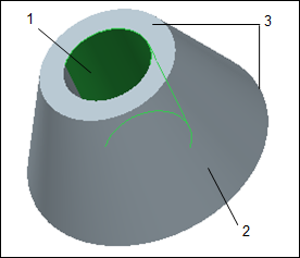
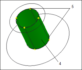
A part made of two concentric cones with variable thickness shell pairs is shown below:
1. top surface
2. bottom surface
3. side surfaces
4. compressed midsurface
5. compressed side surfaces into edges
The side surfaces of the shell pair may not be close to the perpendicular dropped to the midsurface. In such cases, the shell pair thickness may be inaccurate. However the thickness does not exceed the accepted inaccuracies of shell modeling near the element boundaries.


