Constraints on Compressed Midsurfaces
For compressed solid parts in an assembly, Creo Simulate automatically adds, whenever possible, a rigid structural constraint that links compressed curves or surfaces so they are meshed compatibly and will deform together during a run.
Creo Simulate can add this type of constraint when the solid parts are relatively thin—for example, two plates overlapped and mated—and will attempt to add it whenever you run an analysis, or transfer from integrated to independent mode.
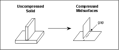
This drawing shows two relatively thin solids with intersecting surfaces. When these solids are compressed to their midsurfaces, there is a physical gap between the intersecting portion of the midsurfaces, and they no longer touch.
The constraints that Creo Simulate adds bridge this gap, and link the overlapping portions of the two compressed surfaces.
If your assembly contains two solids that intersect in a "T" formation, it might look like the drawing below. When these solids are compressed to their midsurfaces, Creo Simulate attempts to add a constraint between the edge of one midsurface and the corresponding area on the other.


