Surface-Surface Gaps
Keep the following points in mind if you want to create gaps between two surfaces:
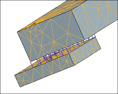
• When you select two surfaces as the gap references, Creo Simulate creates gaps between each of the mesh nodes. In the figure below, Creo Simulate applied a boundary mesh to an assembly with offset-mated surfaces. The purple lines represent the gaps between the mesh nodes.
• If you select the Per Unit Area option under Distribution when you define your surface–surface gap, the software uses the total area of the first surface that you select to calculate the axial and transverse stiffness values. However, if the two surfaces that you select only partially overlap, Creo Simulate first determines the portion of the first surface area that it can use to form a coincident mesh during meshing, and uses that area for the calculation of stiffness values. For example, in the illustration above, if you first selected the top surface on the lower, smaller box for your surface–surface gap definition, Creo Simulate would designate that surface for the Per Unit Area calculation. The actual value the software uses in the calculation would consist of only that surface area with the purple gap icons.
• You can define a gap between two surfaces in a model containing shells compressed to midsurfaces. If you specify your model as a midsurface shell model, and the first surface you select for your gap undergoes midsurface compression to an edge, the software uses the area of the surface before compression for the distribution calculation.

