Example: Unwanted Rotation About a Fastener
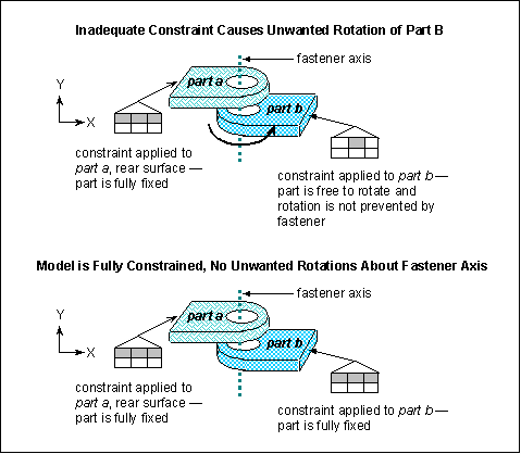
If you do not fully constrain the two components connected by a fastener, one or both of the components will be free to rotate about the fastener axis. In this case, the model may be underconstrained and the Structure engine may fail. The following example illustrates two versions of the model—the first, underconstrained, and the second, correctly constrained.
In the first example, both parts are solids, so there is no need to constrain the component rotations. However, the constraint for part b allows translation in the X- and Y- directions, thus failing to prevent part b from rotating about the fastener axis. In the second example, both parts are fully constrained so there is no unwanted rotation. Even though the parts cannot rotate, you can still model realistic behaviors like flexion at the fastener by placing a force load on the front surfaces near the center-line of the fastener holes.
The previous examples describe fixing rotations using constraints. You can also fix rotations in the following ways:
• Adding other fasteners, provided additional fasteners are acceptable for your model and your model includes reference geometry.
• Creating a contact interface with infinite friction between the parts
• Clearing the Frictionless Interface check box on the Fastener Definition dialog box.

