Detailed Views
1. On the
Layout tab, click
 Detailed View
 from the
Model Views group.
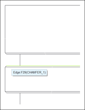
2. From the left view, select the edge of the top groove as shown in the following figure.
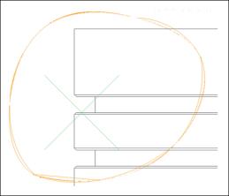
3. Click in the graphics window and sketch a closed spline around the selected groove as shown in the following figure.
4. Middle-click to exit the spline tool.
5. Click in the graphics window to define the CENTER POINT for detailed drawing view.
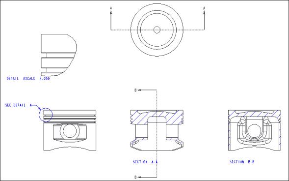
6. Below the new detailed view, double-click the scale value, and change from 2 to 4.
7. To move the views, select any view, right click, and clear the Lock View Movement check box.
8. Click in the empty area of the graphics window to deselect all entities.
9. Right-click in the graphics window, and click General View. The Select Combined State dialog box opens.
10. Ensure that No Combined State is selected and click OK.
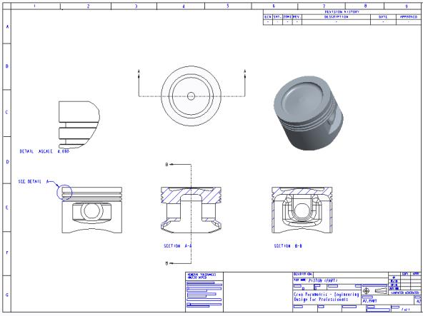
11. Click in the graphics window to define the CENTER POINT of the drawing view as shown in the following figure. The Drawing View dialog box opens.
12. Click OK.


 Detailed View from the Model Views group.

